MR8740、MR8741_user_manual_eng_20191016H.pdf - 第174页
7.9 Setting Details of Modules 162 The anti-aliasing filter (A.A.F) setting is confi gurable for Model 8968 High Resolu tion Unit and Model U8979 Charge Unit only. See: Opening the [Each Ch] sheet, Making a Channel Selec…
7.9 Setting Details of Modules
161
6
Chapter 7 Utility Functions
7
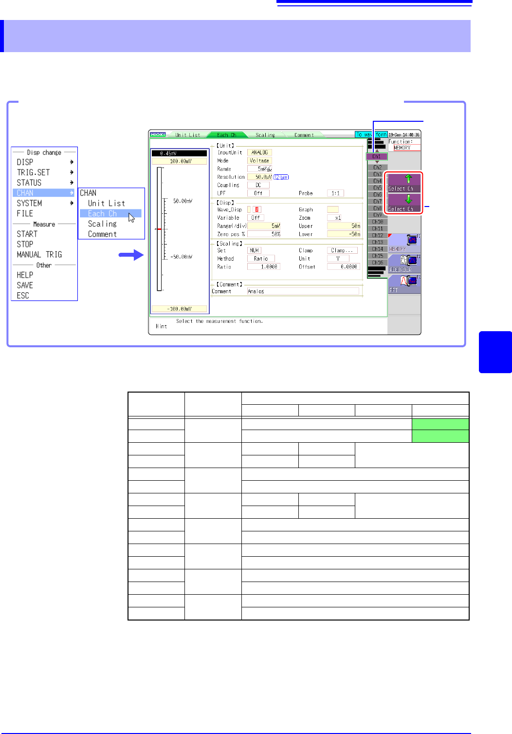
Using the [Each Ch] sheet accessed from the Channel screen, you can make detailed settings.
Logic channel allocation when using Standard LOGIC terminals
*: Ch1 - Ch2 provide 12-bit precision when logic channels LA - LB are used.
When Ch1 to Ch2 are 8970 Freq Unit and standard logic channels LA to LB are
used, the units of corresponding channels can no longer be used.
When the MR8990 Digital Voltmeter Unit is installed on unit 1 (unit 1 or unit 2 in
the case of MR8741), the standard logic can no longer be used.
7.9 Setting Details of Modules
Select
the
channel.
Shows
the chan-
nel num-
ber and
channel
position.
Opening the [Each Ch] sheet, Making a Channel Selection
Click [CHAN] in the right-
click menu.
Module
Memory for each channel (16 bits)
4 bits 4 bits 4 bits 4 bits
Ch1*
Analog
Analog Ch1
LA
Ch2* Analog Ch2
LB
Ch3*
Logic
L2A L2B
-
Ch4* L2C L2D
Ch5
Analog
Analog Ch5
Ch6 Analog Ch6
Ch7
Logic
L4A L4B
-
Ch8 L4C L4D
Ch9
Analog
Analog Ch9
Ch10 Analog Ch10
Ch11
Analog
Analog Ch11
Ch12 Analog Ch12
Ch13
Analog
Analog Ch13
Ch14 Analog Ch14
Ch15
Analog
Analog Ch15
Ch16 Analog Ch16
7.9 Setting Details of Modules
162
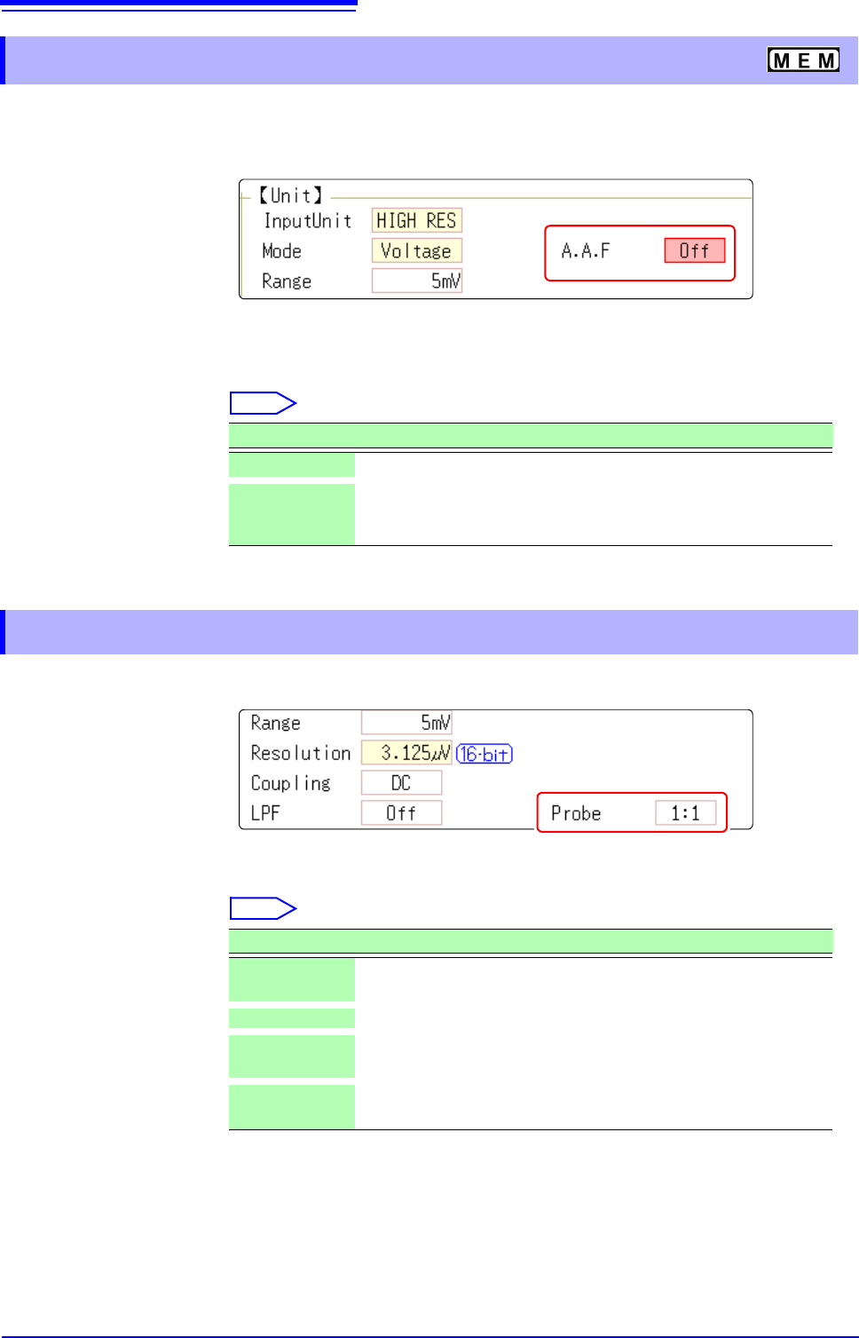
The anti-aliasing filter (A.A.F) setting is configurable for Model 8968 High Resolution Unit and Model
U8979 Charge Unit only.
See: Opening the [Each Ch] sheet, Making a Channel Selection (p.161)
A.A.F Enable the anti-aliasing filter to remove aliasing distortion.
The cutoff frequency automatically changes according to the time axis range or
(when the FFT function is used) the frequency range setting.
Select
See: Opening the [Each Ch] sheet, Making a Channel Selection (p.161)
Probe Make the setting when performing measurement with a connection cable or
probe.
Select
7.9.1 Setting the Anti-aliasing Filter (A.A.F)
Selections Description
Off
The anti-aliasing filter is disabled. (default setting)
On The anti-aliasing filter is enabled.
(When the External sampling is used, the antialiasing filter (AAF) is
not available.)
7.9.2 Probe Attenuation Selection
Selections Description
1:1
Model L9197, L9198 or L9217 Connection Cable connected to the
module. (default setting)
10:1 Model 9665 10:1 Probe connected to the module.
100:1
9666 100:1 Probe, P9000-01/-02 Differential Probe connected to
the module.
1000:1
Model 9322 Differential Probe, P9000-01/-02 Differential Probe
connected to the module.
7.9 Setting Details of Modules
163
6
Chapter 7 Utility Functions
7
See: Opening the [Each Ch] sheet, Making a Channel Selection (p.161)
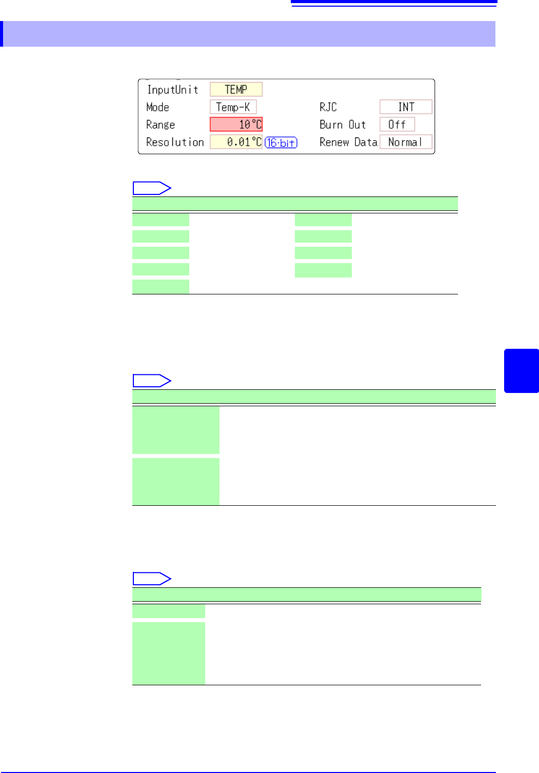
Mode Set to match the type of thermocouple being used.
Select
RJC (Reference
Junction Compen-
sation)
When connecting a thermocouple directly to the module, select [Int].
Reference junction compensation is performed within the module. When con-
necting through a reference junction device (e.g., a 0°C control tank), select
[Ext].
Select
Burn Out A broken thermocouple wire can be detected during temperature measurement.
Normally when a thermocouple wire breaks, measured values exhibit random
instability.
Select
7.9.3 Setting Model 8967 TEMP Unit
Selections Measurement Range Selections Measurement Range
Temp- K
-200 to 1350°C
Temp- R
0 to 1700°C
Temp- J
-200 to 1100°C
Temp- S
0 to 1700°C
Temp- E
-200 to 800°C
Temp- B
400 to 1800°C
Temp- T
-200 to 400°C
Temp- W
0 to 2000°C
Temp- N
-200 to 1300°C
Selections Description
INT
Reference junction compensation is provided within the module.
(default setting)
(Measurement Accuracy: The sum of the accuracies of the temper-
ature measurement and the reference junction compensation.)
EXT Reference junction compensation is not provided within the mod-
ule.
(Measurement Accuracy: The accuracy of temperature measure-
ment only)
Selections Description
Off
Broken wires are not detected.
On Broken wires are detected.
Wire breakage is detected by sensing a miniscule current flow
(about 100 nA) through the thermocouple. If the thermocouple
wires are long or composed of a high-resistance material, set [Burn
Out] to [Off] to avoid measurement errors.