MR8740、MR8741_user_manual_eng_20191016H.pdf - 第24页
Operating Precau tions 12 Before Connecting a Logic Probe to the Measurement Object T o avoid electric shock and short circuit ac cidents or damage to the instru- ment, pa y attention to the following: • The ground pin i…
Operating Precautions
11
Before Connecting Cables
When measuring power line voltage
• Connecting cables should only be connected to the secondary side of a
breaker Even if there is a short circuit on the secondary side of the breaker, the
breaker cuts off the electric supply. Do not connect to the primary side of a
breaker because unrestricted current flow could damage the instrument and
facilities if a short circuit occurs.
• To prevent electrical shocks and personal injury, do not touch any input termi-
nals on the VT (PT), CT or the instrument when they are in operation.
• Do not permanently connect the instrument in an environment where voltage
surges exceeding the maximum input voltage may occur. Applying voltage
may result in damage to the instrument, or a serious accident.
• Do not short-circuit two wires to be measured by bringing the connection
cables into contact with them. Arcs or such grave accidents are likely to occur.
• To avoid short circuit or electric shock, do not touch the metal parts of the con-
necting cable clips.
• To avoid electrical shocks, be careful to avoid shorting live lines with the con-
nection cable clips.
• To avoid electric shock and short-circuit accidents, use only the specified test
leads to connect the instrument input terminals to the circuit to be tested.
• To prevent an electric shock, confirm that the white or red portion (insulation
layer) inside the cable is not exposed. If a color inside the cable is exposed, do
not use the cable.
• The cable is hardened under the 0°C (32°F) or colder environment. Do not
bend or pull cables in such environments to avoid tearing insulation or break-
ing the cable.
•
Connecting to the BNC jacks on modules
Do not use a metal BNC connector. If you connect a metal BNC cable to an
insulated
BNC connector, the insulated BNC connector can be damaged and the instru-
ment may be damaged.
• To prevent cable damage, do not step on the cable or pinch them between
other objects. Do not bend or pull cables at their base.
• Use only the specified connection cables. Using a non-specified cable may
satisfy the specification requirements due to poor connection or other reasons.
• For detailed precautions and instructions regarding connections, refer to the
instruction manuals for your modules, connection cables, etc.
Operating Precautions
12
Before Connecting a Logic Probe to the Measurement Object
To avoid electric shock and short circuit accidents or damage to the instru-
ment, pay attention to the following:
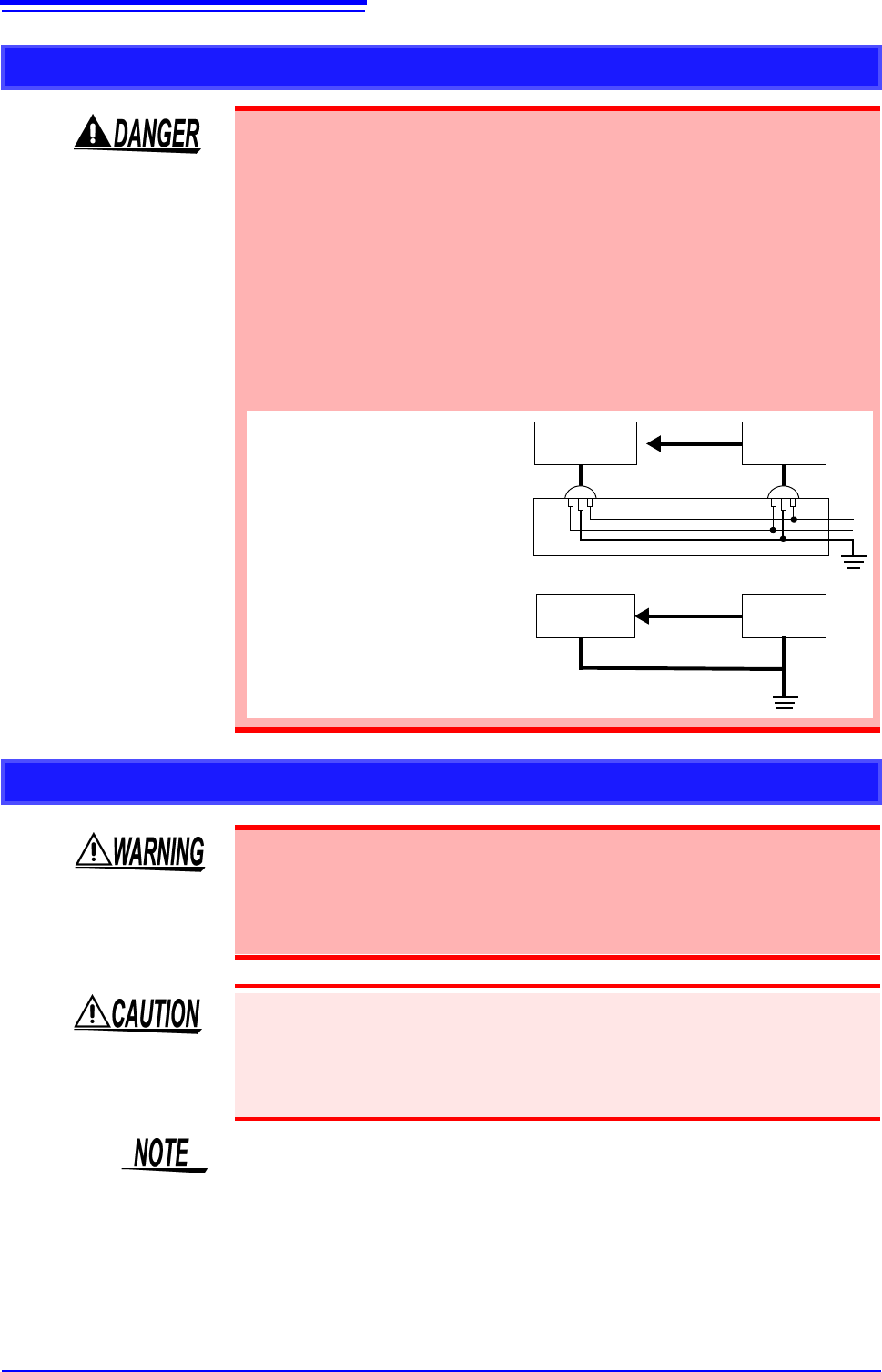
• The ground pin in the LOGIC connector (plug) of the Model 9320-01 and
9327 Logic Probes (and legacy Models 9306 and 9320) is not isolated
from this instrument’s ground (common ground).
Use grounding-type polarized power cords for the measurement object
and this instrument, and obtain power from the same mains circuit.
Connecting to different mains circuits or using a non-grounding power
cord may cause damage to the measurement object or this instrument
because of current flow through the logic probes resulting from potential
difference between the grounds of the different wiring systems.
To avoid these problems, we recommend the following connection pro-
cedure:
Measurement
Object
Memory
HiCorder
Logic probe
Connect this instrument to the same
outlet as the measurement object us-
ing the (supplied) grounding polar-
ized power cord.
ground to the GND terminal
(functional earth terminal) of this
instrument.
(Always obtain power from the
same mains circuit.)
Measurement
Object
Logic probe
Functional
Earth Termi-
nals
GND
Memory
HiCorder
Before Turning the Power Supply On
• To avoid electrical accidents and to maintain the safety specifications of this
instrument, connect the power cord provided only to an outlet.ïï
• Before turning the instrument on, make sure the supply voltage matches that
indicated on its power connector. Connection to an improper supply voltage
may damage the instrument and present an electrical hazard.
• Avoid using an uninterruptible power supply (UPS), DC/AC inverter with rect-
angular wave or pseudo-sine-wave output to power the instrument. Doing so
may damage the instrument.
• To avoid damaging the power cord, grasp the plug, not the cord, when unplug-
ging it from the power outlet.
Turn off the power before disconnecting the power cord.
Operating Precautions
13
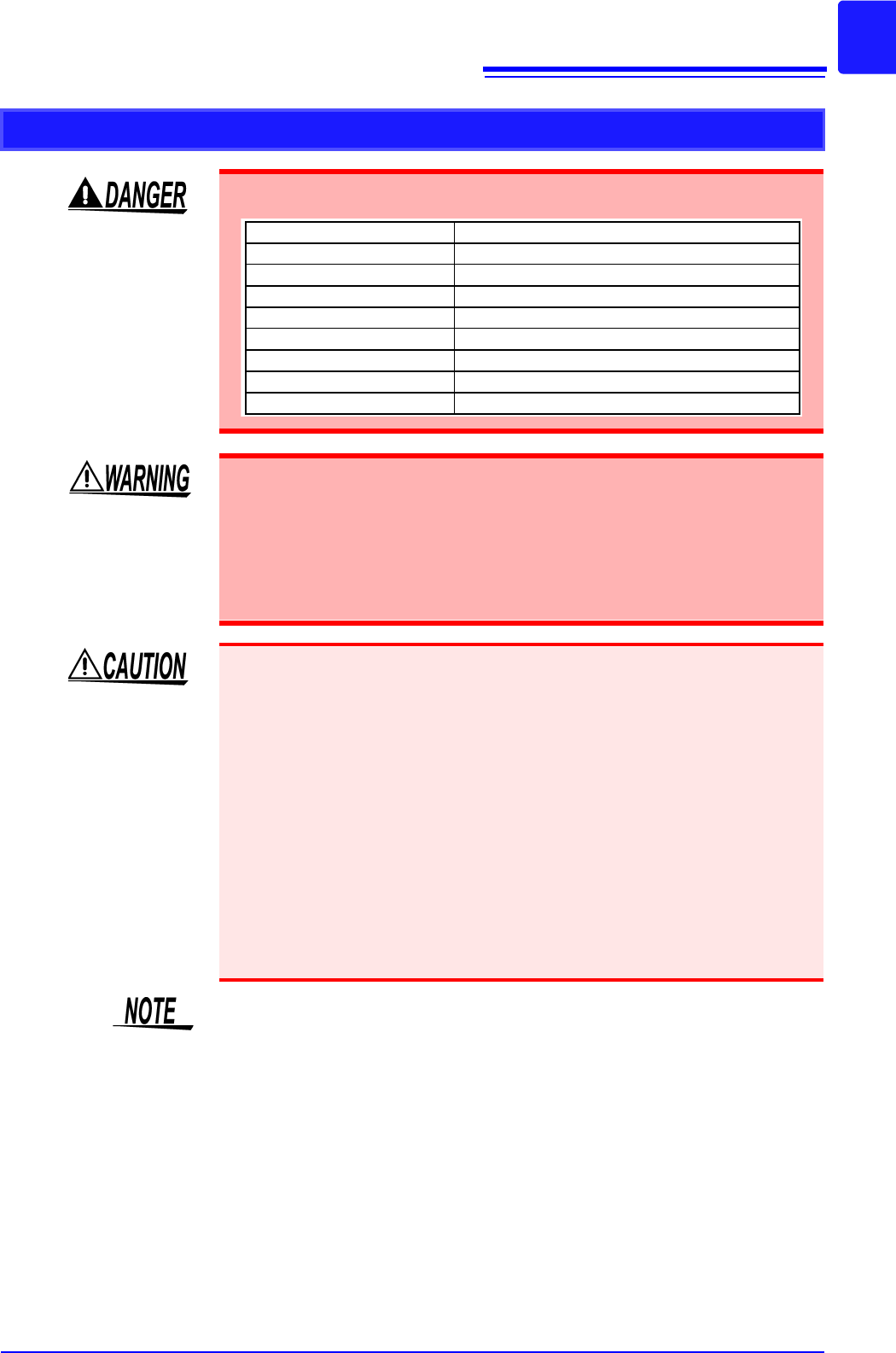
Before Connecting to an External Device (model MR8741 only)
To avoid electrical hazards and damage to the instrument, do not apply voltage
exceeding the rated maximum to the input terminals.
I/O terminals Maximum input voltage
START/IN1 -0.5 V to 7 V DC
STOP/IN2 -0.5 V to 7 V DC
SAVE/IN3 -0.5 V to 7 V DC
GO/OUT1 50 V DC 50 mA 200 mW
NG/OUT2 50 V DC 50 mA 200 mW
SMPL -0.5 V to 7V DC
TRIG OUT 50 V DC 50 mA 200 mW
EXT.TRIG -0.5 to 7 V DC
To avoid electric shock or damage to the equipment, always observe the follow-
ing precautions when connecting to external control terminals.
• Always turn off the power to the instrument and to any devices to be connected
before making connections.
• Be careful to avoid exceeding the ratings of external terminals and connectors.
• Ensure that devices and systems to be connected to the External control termi-
nals are properly isolated.
The ground pins of external control connectors are not isolated from the instru-
ment’s ground. Connect so that no potential difference arise between external con-
trol connector ground and the ground of the connection object. Failure to observe
this precaution can result in damage to the connection object and the instrument.
• Use a common ground for both the instrument and the connection equipment.
• Use of different ground circuits will result in a potential difference between the
instrument’s ground and the connected equipment’s ground. If the communica-
tions cable is connected while such a potential difference exists, it may result
in equipment malfunction or failure.
• While connecting or disconnecting the communication cables, ensure that the
power supply of the instrument and the device to be connected is cut off. This
may cause damage or malfunctioning.
• After connecting the communications cable, tighten the screws on the connec-
tor securely. Failure to secure the connector could result in equipment mal-
function or damage.
MR8740 does not support external control.