MR8740、MR8741_user_manual_eng_20191016H.pdf - 第32页
1.4 Screen Configuration 20 Explanation of Screen Cont ent s _____________ _____________________ W aveform Screen Logic waveform (p.79) Analog waveform (p.76) Stora ge counter Shows how many trigger events occurred . (p.…
1.4 Screen Configuration
19
1
Chapter 1 Overview
The screen configuration is shown below. Click an item with the mouse to display the corresponding
screen.
On the Waveform screen, the trigger settings window and channel settings window can be displayed.
1.4 Screen Configuration
Status Screen
This screen is for making settings for the measurement method and numerical calcula-
tion of waveform data.
There are the following sheets: [Status] sheet, [Num Calc] sheet, [Memory Div] sheet,
[Wave Calc] sheet
STATUS
Waveform Screen
This screen is for observing waveforms.
The settings window on the right shows the measurement parameters.
Trigger Settings Window/Channel Settings Window
This window is for making the advanced settings for triggers.
This window is for making the advanced settings for analog channels and logic channels.
Channel Screen
This screen is for making channel settings, scaling settings, and comment settings.
There are the following sheets: [Unit List] sheet, [Each Ch] sheet, [Scaling] sheet,
[Comment] sheet
System Screen
This screen is for making settings for the environment, file saving, and communication,
and for performing data initialization.
There are the following sheets: [Environment] sheet, [File Save] sheet, [Printer] sheet,
[Interface] sheet, [Init] sheet
File Screen
This screen is for viewing the data files on media (USB memory stick and internal
memory).
DISP
TRIG.SET
CH.SET
CHAN
SYSTEM
FILE
1.4 Screen Configuration
20
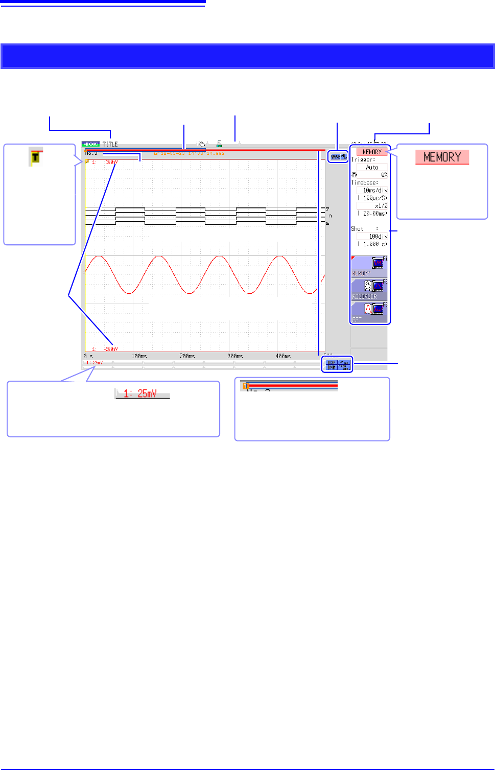
Explanation of Screen Contents __________________________________
Waveform Screen
Logic waveform (p.79)
Analog waveform (p.76)
Storage counter
Shows how many trigger events occurred. (p.82)
Current date
and time
Shows the set date
and time. (p.57)
Settings cursor
The current cursor lo-
cation is indicated by
flashing.
Title comment
Shows the set title com-
ment. (p.138)
Trigger
marker
Shows the point
where the trigger
event occurred.
(p.189)
Settings window
Set the measurement pa-
rameters here. (p.65)
Trigger time
Shows the date and
time of the last trig-
ger event. (p.189)
Vertical axis display
Shows the value per increment for each channel. This is
linked to the vertical axis (voltage axis) range setting.
(p.76)
Upper and
lower limits
The upper and lower
limit values for each
channel are shown
here. (p.134)
Scroll bar
The stored waveform is indicated by a
red bar, and the displayed waveform by a
blue frame. (p.125)
Media icon
Shows the media status.
(p.53)
Operation icons
Left-click to scroll the wave-
form or operate the A/B cur-
sors.
Display and setting
icons
Left-click to display the
waveforms and numerical
values or make channel
settings.
1.4 Screen Configuration
21
1
Chapter 1 Overview
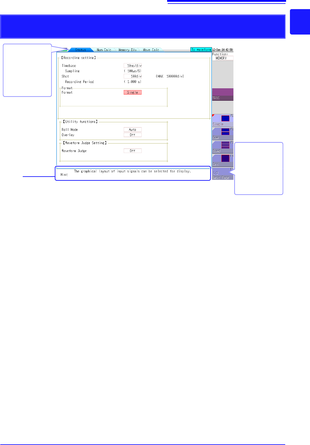
Elements common to the Status screen, Channel screen, System screen, and
File screen
Sheet tabs
Shows the names of
sheets that can be
selected.
Click a tab to switch
to the corresponding
sheet.
Hint
Shows an explanation about the item where the settings cursor is currently located.
Messages such as "Online" and error messages are also shown here.
Next Page
This is shown if there
are more than six se-
lection items.
Selecting this button
displays the other
items.