MR8740、MR8741_user_manual_eng_20191016H.pdf - 第175页
7.9 Setting Details of Modules 163 6 Chapter 7 Utility Functions 7 See: Opening the [Each Ch] sheet, Making a Channel Sele ction (p.161) Mode Set to match the type of thermocouple being used. Select RJC (Reference Juncti…
7.9 Setting Details of Modules
162
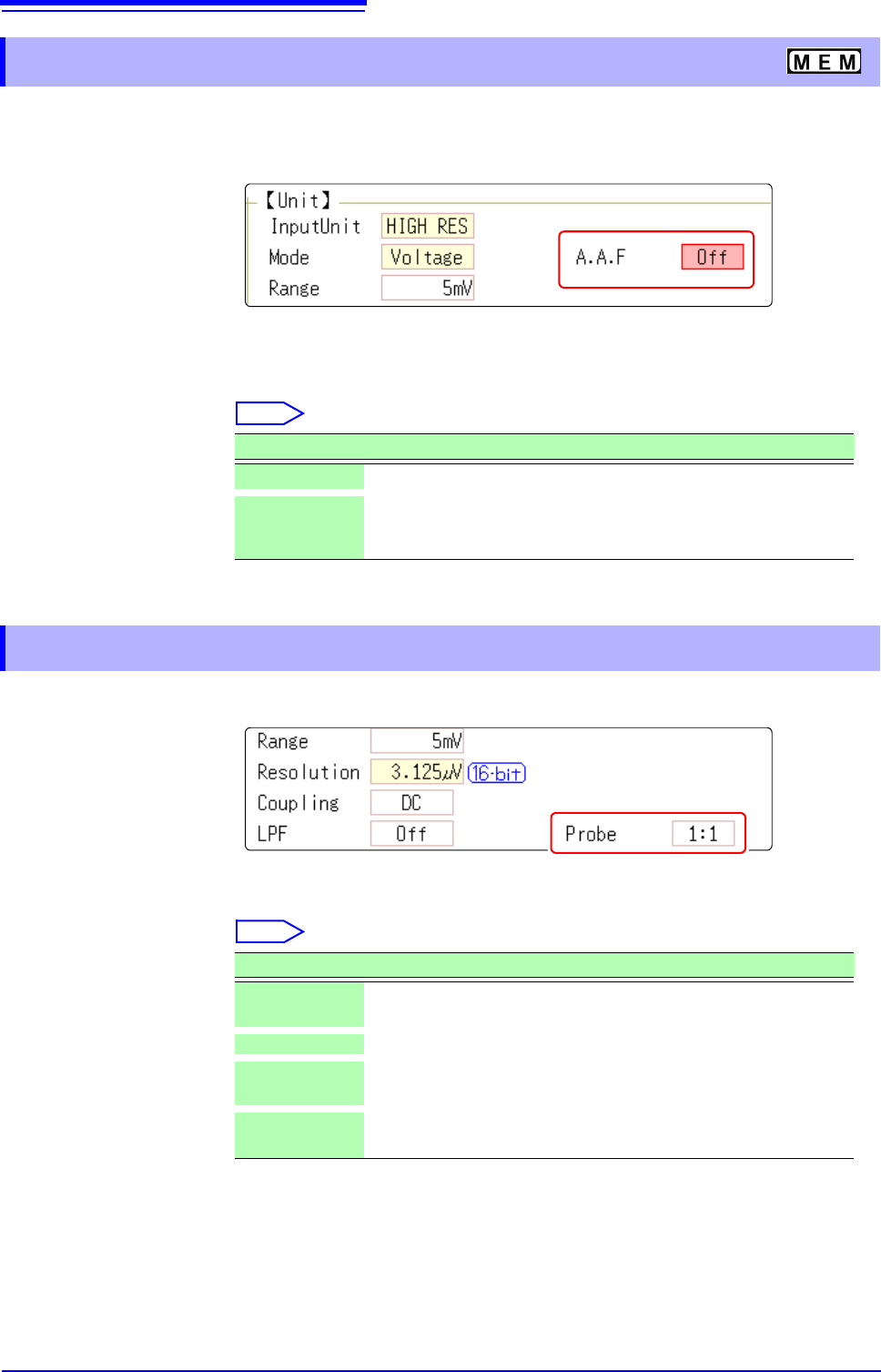
The anti-aliasing filter (A.A.F) setting is configurable for Model 8968 High Resolution Unit and Model
U8979 Charge Unit only.
See: Opening the [Each Ch] sheet, Making a Channel Selection (p.161)
A.A.F Enable the anti-aliasing filter to remove aliasing distortion.
The cutoff frequency automatically changes according to the time axis range or
(when the FFT function is used) the frequency range setting.
Select
See: Opening the [Each Ch] sheet, Making a Channel Selection (p.161)
Probe Make the setting when performing measurement with a connection cable or
probe.
Select
7.9.1 Setting the Anti-aliasing Filter (A.A.F)
Selections Description
Off
The anti-aliasing filter is disabled. (default setting)
On The anti-aliasing filter is enabled.
(When the External sampling is used, the antialiasing filter (AAF) is
not available.)
7.9.2 Probe Attenuation Selection
Selections Description
1:1
Model L9197, L9198 or L9217 Connection Cable connected to the
module. (default setting)
10:1 Model 9665 10:1 Probe connected to the module.
100:1
9666 100:1 Probe, P9000-01/-02 Differential Probe connected to
the module.
1000:1
Model 9322 Differential Probe, P9000-01/-02 Differential Probe
connected to the module.
7.9 Setting Details of Modules
163
6
Chapter 7 Utility Functions
7
See: Opening the [Each Ch] sheet, Making a Channel Selection (p.161)
Mode Set to match the type of thermocouple being used.
Select
RJC (Reference
Junction Compen-
sation)
When connecting a thermocouple directly to the module, select [Int].
Reference junction compensation is performed within the module. When con-
necting through a reference junction device (e.g., a 0°C control tank), select
[Ext].
Select
Burn Out A broken thermocouple wire can be detected during temperature measurement.
Normally when a thermocouple wire breaks, measured values exhibit random
instability.
Select
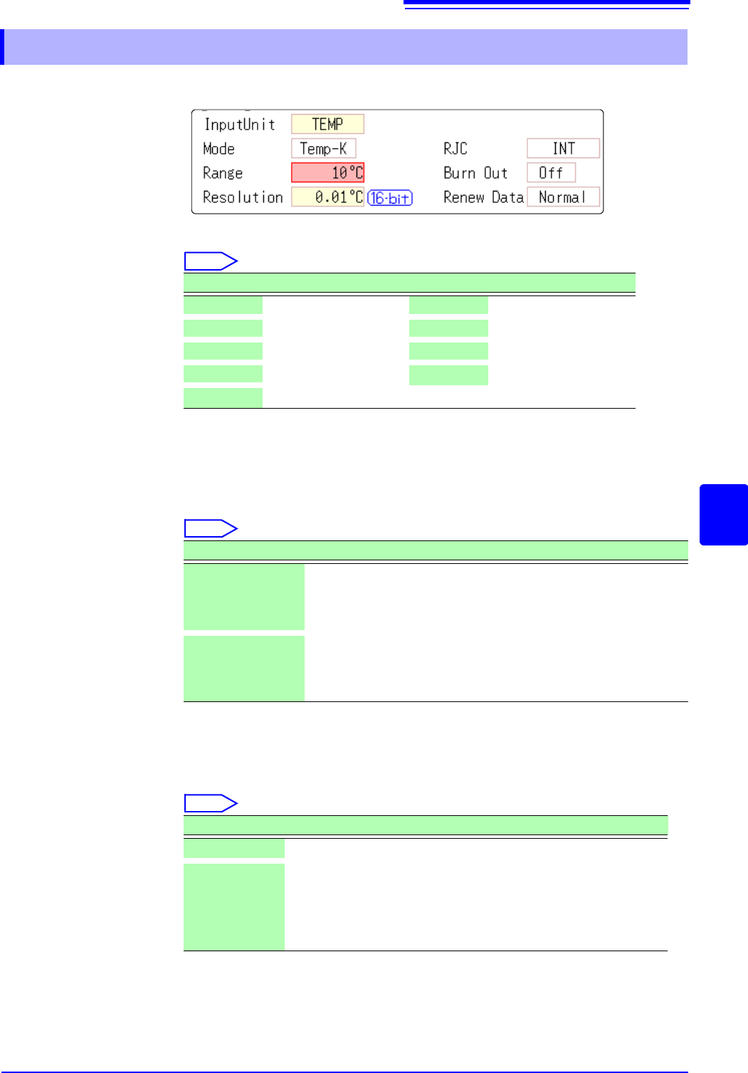
7.9.3 Setting Model 8967 TEMP Unit
Selections Measurement Range Selections Measurement Range
Temp- K
-200 to 1350°C
Temp- R
0 to 1700°C
Temp- J
-200 to 1100°C
Temp- S
0 to 1700°C
Temp- E
-200 to 800°C
Temp- B
400 to 1800°C
Temp- T
-200 to 400°C
Temp- W
0 to 2000°C
Temp- N
-200 to 1300°C
Selections Description
INT
Reference junction compensation is provided within the module.
(default setting)
(Measurement Accuracy: The sum of the accuracies of the temper-
ature measurement and the reference junction compensation.)
EXT Reference junction compensation is not provided within the mod-
ule.
(Measurement Accuracy: The accuracy of temperature measure-
ment only)
Selections Description
Off
Broken wires are not detected.
On Broken wires are detected.
Wire breakage is detected by sensing a miniscule current flow
(about 100 nA) through the thermocouple. If the thermocouple
wires are long or composed of a high-resistance material, set [Burn
Out] to [Off] to avoid measurement errors.

7.9 Setting Details of Modules
164
Renew Data
(Data Refresh)
The data refresh rate can be set to Fast, Normal, or Slow.
The default setting is [Normal]. This allows stable measurement while removing
noise. For quicker response, select [Fast], but note that this will make the mea-
surement more susceptible to noise. For further improved measurement stability,
select [Slow].
Select
Selections Description
Fast
Data are updated approximately every 1.2 ms.
Normal
Data are updated approximately every 100 ms. (default setting)
Slow
Data are updated approximately every 500 ms.