MR8740、MR8741_user_manual_eng_20191016H.pdf - 第64页
2.2 Connecting Cords 52 Output connect or 10250-52A2PL: Sumitomo 3M products (SCSI-2 connecto r), (Centronics half-pitch 50 pin socket-contact) Refer to "Output Connector Specifications" ( p.370). • Met al shel…
2.2 Connecting Cords
51
2
Chapter 2 Measurement Preparations
Applicable Modules
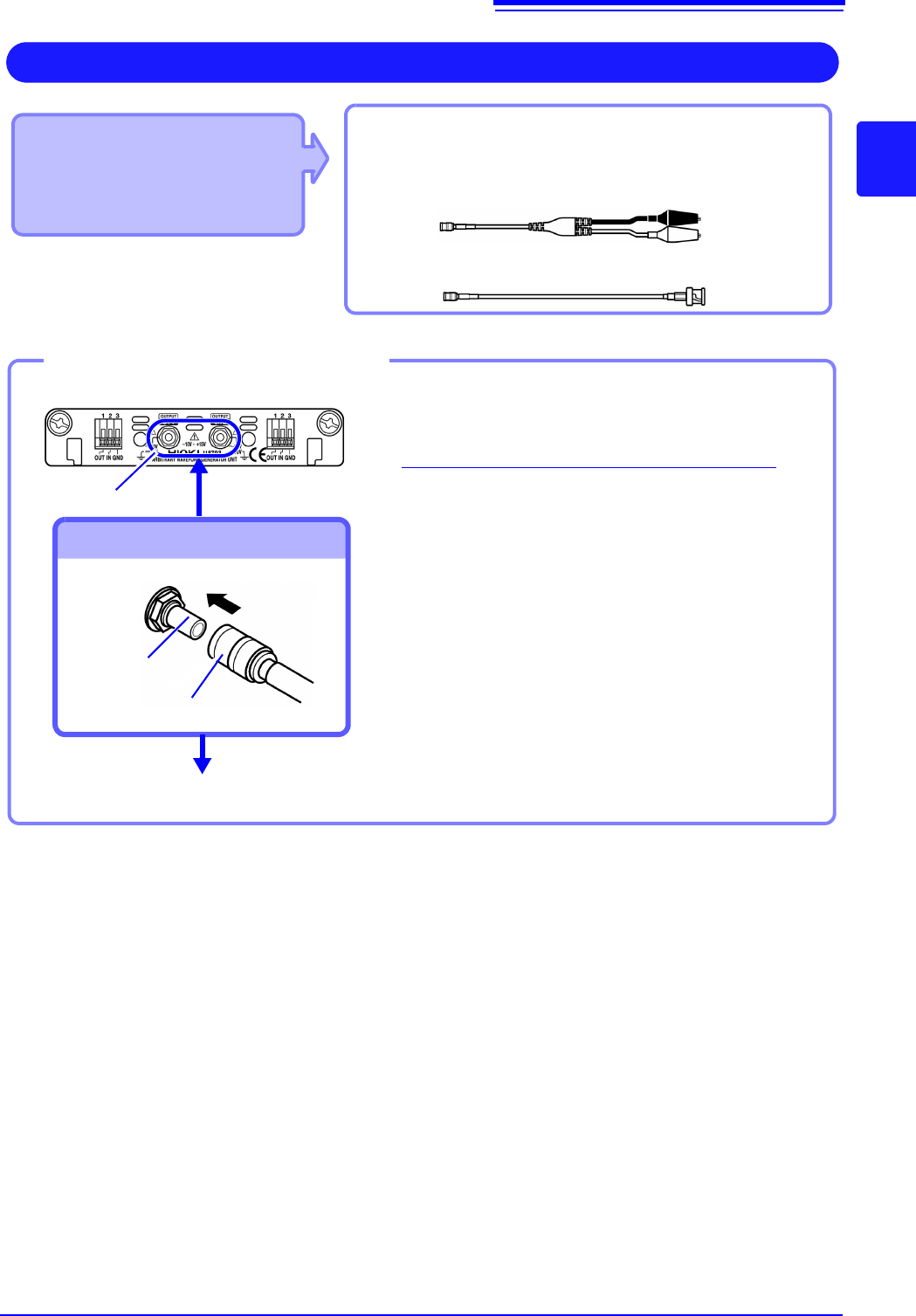
• Model U8793 Arbitrary
Waveform Generator Unit
• Model MR8790 Waveform
Generator Unit
Required item: Model L9795-01 /L9795-02 Connection
Cableconnect: L2200 Test Lead
Output Waveform
Connect to the SMB jack on a module.
• Model L9795-01 Connection Cable (Electrical clips)
• Model L9795-02 Connection Cable (BNC output)
1
Insert the SMB connector of connection cable
in the output terminal of the module until you
hear a click.
2
Connect the cable clips to the object to which
the waveform is being applied.
Required items: Connection cable mentioned above
Output terminal
To Connect to Output Terminals
Connect the Connection cable
To disconnect output connectors
Grip the head of the SMB connector (not the cable),
and pull it out.
Output terminal
SMB connector
Connect to the object to which the waveform is being applied.
Example: Model U8793
1
2
2.2 Connecting Cords
52
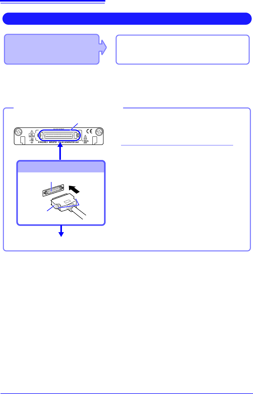
Output connector
10250-52A2PL: Sumitomo 3M products (SCSI-2 connector), (Centronics half-pitch 50 pin socket-contact)
Refer to "Output Connector Specifications" ( p.370).
• Metal shell of the connector 10250-52A2PL is the same as GND of the instrument (frame GND).
• Use lock type connectors for connecting the harness and the connector.
Applicable Module
• Model MR8791 Pulse Generator Unit
Required items: Commercially available cable
(Half-pitch 50 pins)
Output Pulse Waveform
Connect to the banana jacks on a module.
1
Connect the connection cable to Output
Connector of module.
2
Connect the connection cable to the object to
which the waveform is being applied.
Required items: Commercially available cable
To Connect to Output Connector
Connect the Connection cable
To disconnect output connectors
Hold the button of connection cable while pulling the
connector.
Button
Connect to the object to which the waveform is being applied.
Example: Model U8793
Output connector
Connection cable
connector
Output connector
2
1
2.3 Recording Media Preparation
53
2
Chapter 2 Measurement Preparations
Read "Handling Media" ( p.10) carefully.
Media icons Icons indicating the status of storage media are always shown at the top of the
screen.
2.3 Recording Media Preparation
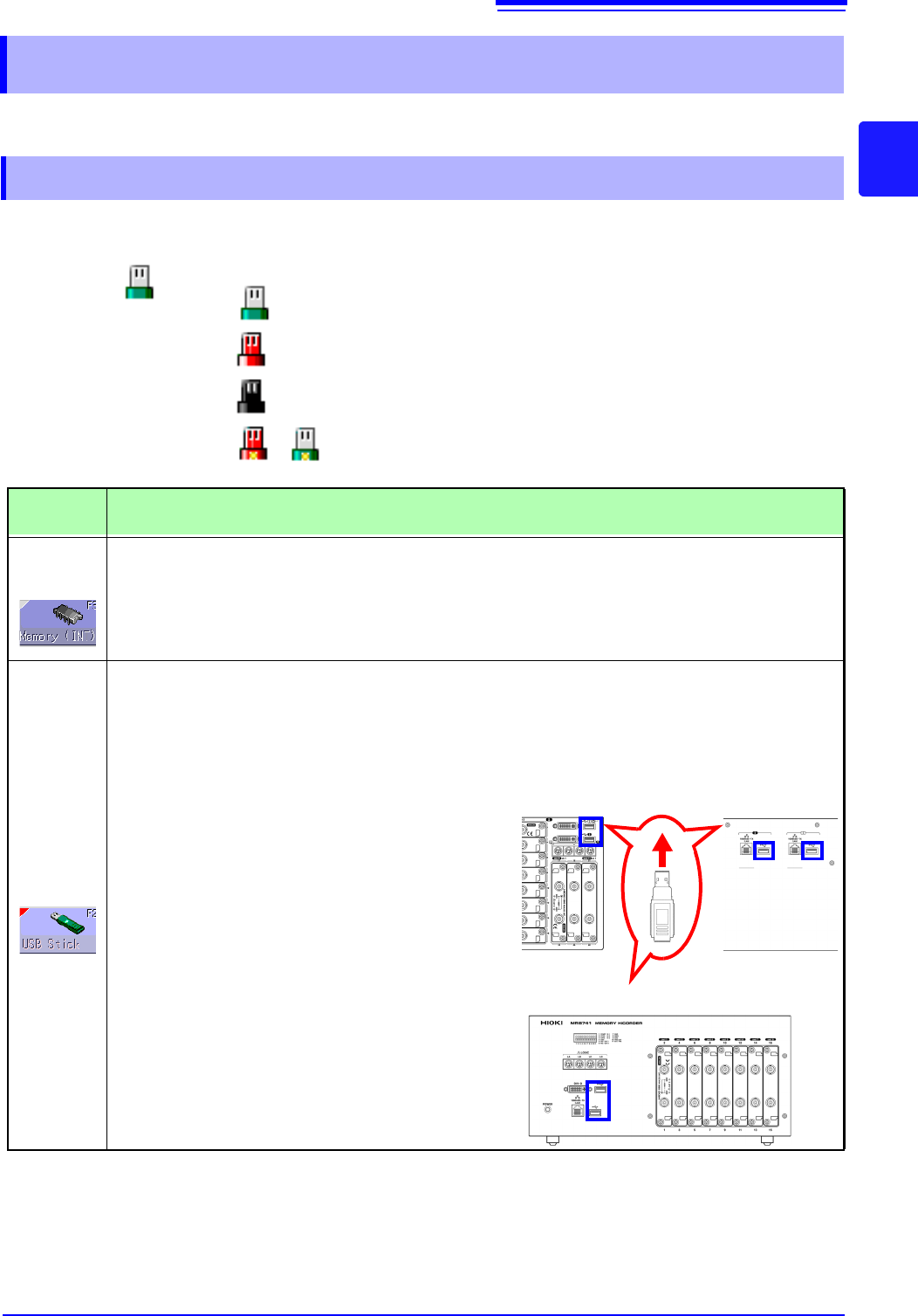
2.3.1 Storage Media (Inserting a USB Memory Stick)
USB
memory
stick
: Media is inserted
: Media is inserted and selected as save target (Icon col-
or is red)
: Media is not inserted but selected as save target (Icon
color is black)
: The center part of the icon appears yellow while the
USB memory stick is being accessed.
Storage
Media
Inserting procedure, Remarks, and Notes
RAM
(Internal
memory)
• Memory integrated in the unit is used. Only settings can be stored.
• Automatic saving of data is not possible.
USB
memory
stick
Inserting a USB memory stick
Ensure correct orientation of the USB memory
stick and push it all the way into the connector.
Remove a USB memory stick
Verify that the unit is not accessing the USB mem-
ory stick (for saving or loading data, etc.). Then
pull the USB memory stick out. (No special steps
are required at the instrument.)
USB Connector (Type A)
• Do not connect any devices other than USB memory stick.
• Not all commonly available USB memory sticks are supported.
• To use a USB memory stick, suitable unit settings must be made,
as described below.
Front Side
Back Side
MR8740
Front Side
MR8741