MR8740、MR8741_user_manual_eng_20191016H.pdf - 第405页
Appendix 2 Reference A 9 Appendix This section describes how to determine the scal ing conversion ratio when measuring with st rain gauges and the Model 89 69 and U8969 Strain Unit. The appropriate conver sion formula fo…
Appendix 2 Reference
A8
*: If the data update rate specified at NPLC is longer than the sampling rate indicated in the table above, one
of data is measured repeatedly during the data update rate period.
See:"7.9.8 Setting Model MR8990 Digital Voltmeter Unit" ( p.171)
*: If the time axis range is set to one faster than 100 ms/div, one of data is measured repeatedly during the
data update rate period specified at NPLC.
See:"7.9.8 Setting Model MR8990 Digital Voltmeter Unit" ( p.171)
Fixed record length
The number of
divisions
(blocks)
Maximum record
length (div)
250,000
420,000
820,000
16 10,000
32 5,000
64 2,000
128 1,000
256 500
512 200
1024 100
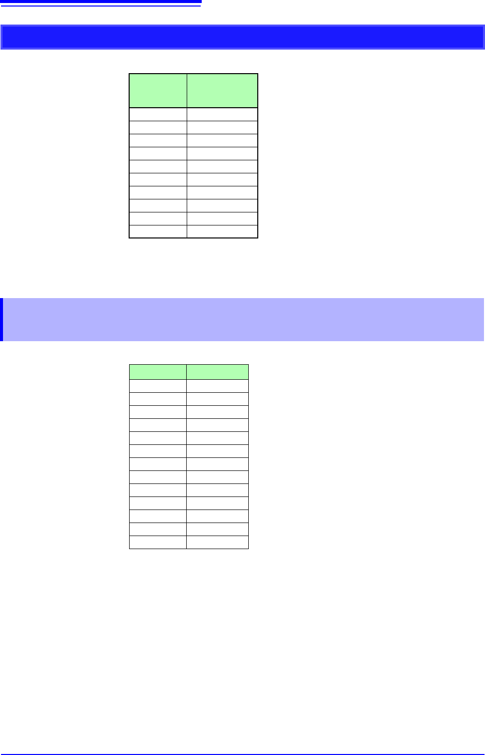
Appendix 2.5 Time Axis Range and Sampling Rate of
MR8990 Digital Voltmeter Unit
Timebase/div Sampling Rate
100 ms 2 ms
200 ms 4 ms
500 ms 10 ms
1 s 20 ms
2 s 40 ms
5 s 100 ms
10 s 200 ms
30 s 600 ms
50 s 1 s
1 min 1.2 s
10 s 2 s
2 min 2.4 s
5 min 6 s

Appendix 2 Reference
A9
Appendix
This section describes how to determine the scaling conversion ratio when measuring with strain
gauges and the Model 8969 and U8969 Strain Unit.
The appropriate conversion formula for stress depends on how the strain gauges
are used.
Three methods are available depending on whether one, two or four strain
gauges are used for measurement. The two-gauge method is used for tempera-
ture compensation.
E: Young modulus, : Poisson ratio, : Distortion measurement value
Tensile and Compressive Stress Measurement: Stress () = E ×
For temperature compensation with two or four gauges, position the gauges per-
pendicularly.
Stress () is obtained by 1 / (1 + ) for two gauges, and by 1 / {2 (1 + )} for four
gauges.
Bending Stress Measurement: Stress () = E
×
For temperature compensation with two or four gauges, stress () is obtained as
a multiple of ½ or ¼, respectively.
Torsional Stress Measurement: Stress () = E / {2 (1 + )} × (two-gauge case)
For the four-gauge case, it is half of that.
Refer to the strain gauge instruction manual for combinations of strain gauges
for each measurement.
Example. Measuring Compressive Stress
Using the one-gauge method for an aluminum measurement object having a
Young's modulus of 73 (GPa) according to the following Table,
= 73 × 10
9
× Measurement Value (in units) × 10
-6
(in units)
) = 73 × Measurement Value (in kPa units)
= 7.44
*
× Measurement Value (in gf/mm
2
units)
*:
1 Pa = 1.01971621× 10
-7
kgf/mm
2
Unit: gf/mm
2
, Conversion Ratio = 7.44 gf/mm
2
Enter this value as the scaling conversion ratio
See: "7.4 Converting Input Values (Scaling Function)" (p.148)
Appendix 2.6 Scaling Method When Using Strain
Gauges
Mechanical properties of industrial materials
Material
Modulus of Elasticity
(Young's Modulus)
Poisson's Ratio
E (GPa)
Carbon Steel (0.1 to 0.25% C)
205 0.28 to 0.3
Carbon Steel (> 0.25% C) 206 0.28 to 0.3
Spring Steel (Quenched) 206 to 211 0.28 to 0.3
Nickel Steel 205 0.28 to 0.3
Cast Iron 98 0.2 to 0.29
Brass (Cast) 78 0.34
Phosphor Bronze 118 0.38
Aluminum 73 0.34
Concrete 20 to 29 0.1
Appendix 3 About Options
A10
The following options are available for the instrument. Contact your authorized Hioki distributor or
reseller when ordering. The options are subject to change. Visit our website for updated information.
For details of cables and clamps for connecting to the modules and the instrument, refer to manual
supplied with them.
Items indicated "specify when ordering" are not user-installable. For new purchases, contact your supplier
(agent) or nearest Hioki office.
Appendix 3 About Options
Appendix 3.1 Options
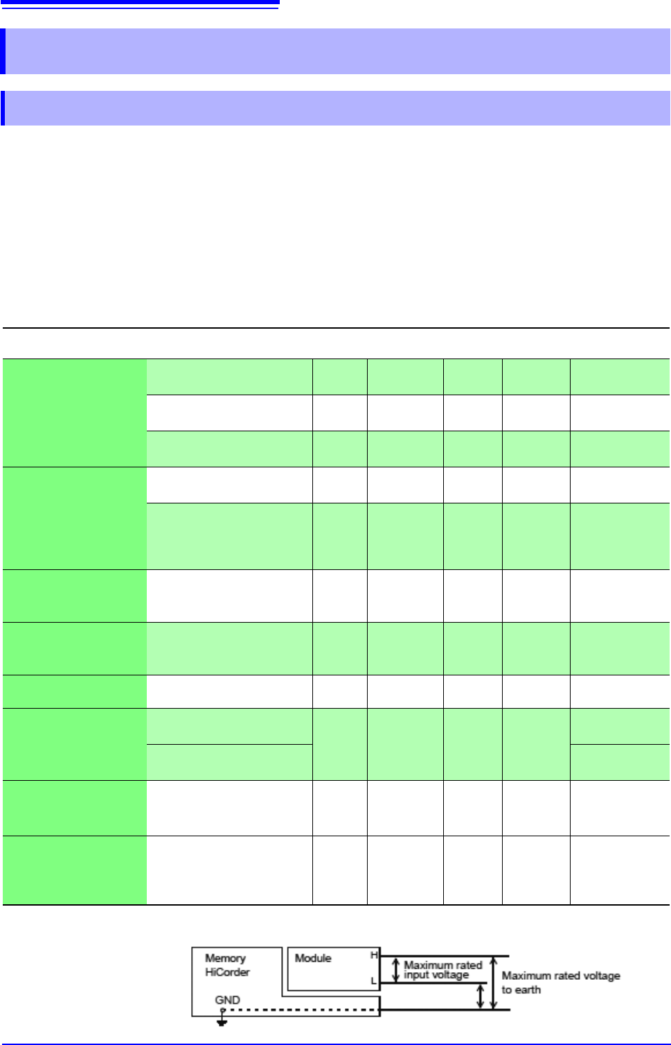
Modules (Measurement amplifiers)
These are installed by insertion into the compartments on the right side of the instrument. Modules can be swapped out as
needed.
Application Model Channels
Max Sampling
Rate
A/D
Resolution
Maximum
input voltage
Maximum rated
voltage to earth
Voltage
measurements
Model 8966 Analog Unit
2 20 MS/s 12 bits 400 V DC
300 V AC, DC
(CAT II)
Model 8968 High Resolution
Unit
2 1 MS/s 16 bits 400 V DC
300 V AC, DC
(CAT II)
Model MR8990 Digital
Voltmeter Unit
2 500 S/s 24 bits 500 V DC
300 V AC, DC
(CAT II)
RMS voltage
measurements
Model 8972 DC/RMS Unit 2 1 MS/s 12 bits 400 V DC
300 V AC, DC
(CAT II)
Model U8974 High Volteage
Unit
2 1 MS/s 16 bits
1000 V DC
700 V AC
1000 V AC, DC
(CAT III)
600 V AC, DC
(CAT IV)
Temperature
(Thermocouple)
measurements
Model 8967 TEMP Unit 2 - 16 bits -
300 V AC, DC
(CAT II)
Frequency, count,
pulse duty, and pulse
width measurements
Model 8970 Freq Unit 2 - 16 bits 400 V DC
300 V AC, DC
(CAT II)
Current Measurement
(model 8741 only)
Model 8971 Current Unit 2 1 MS/s 12 bits -
Not insulated
Strain (Strain gauge
type converter)
measurements
Model 8969 Strain Unit
2 200 kS/s 16 bits -
33 V rms AC or
70 V DC
Model U8969 Strain Unit
30 V rms AC or
60 V DC
Digital signals
and contact signal
measurement
Model 8973 Logic Unit 16 20 MS/s - -
Not insulated
Acceleration measure-
ment (sensor with built-
in preamplifier, charge-
output sensor)
Model U8979 Charge Unit 2 200 kS/s 16 bits 40 V DC
30 V AC,
60 V DC
See: "17.6 Specifications of Modules" (p.352)