MR8740、MR8741_user_manual_eng_20191016H.pdf - 第51页
2.2 Connecting Cords 39 2 Chapter 2 Measurement Prep arations Read "Before Connecting Cables " ( p.11) carefully. For detailed precautions and instr uctions regarding co nnections, refer to the instruction manu…
2.1 Installing and Removing Modules
38
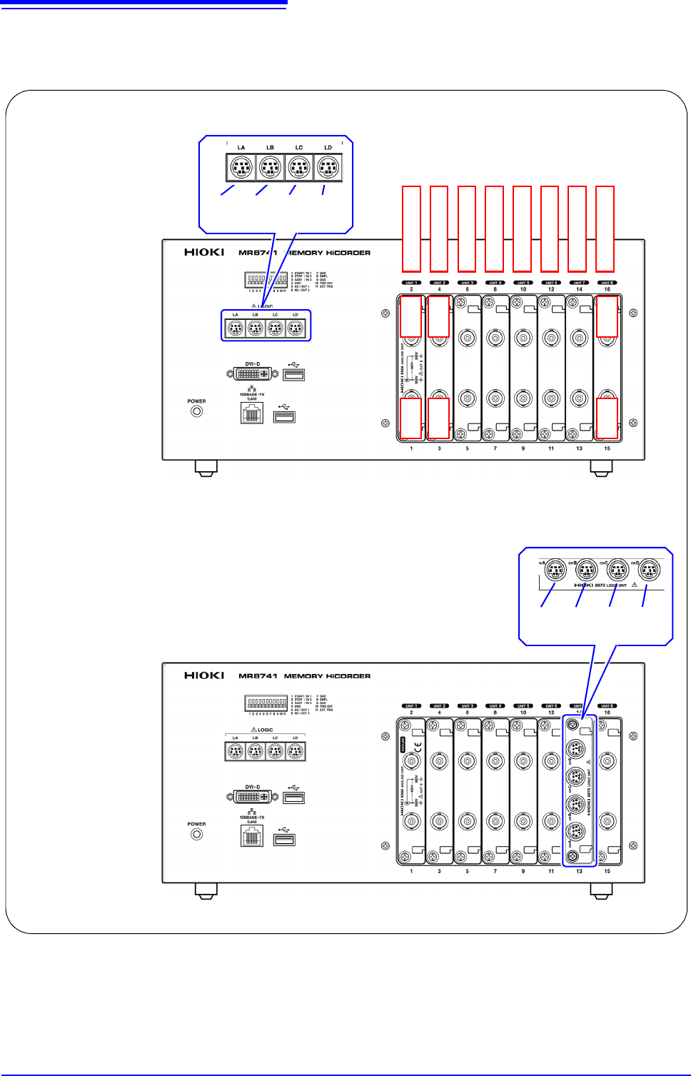
MR8741 The module numbers are in order starting with one at the left, and the channel
numbers are in order starting with one at the bottom of the module at the very
left.
Analog channels only
Ch1 Ch2
LA LB LC LD
[1:4] [1:4] [1:4] [1:4]
Module 1
Module 2
Module 3
Module 4
Module 5
Module 6
Module 7
Module 8
Mix including logic units
Ch3 Ch4
Ch15 Ch16
L7A L7B L7C L7D
[1:4] [1:4] [1:4] [1:4]
2.2 Connecting Cords
39
2
Chapter 2 Measurement Preparations
Read "Before Connecting Cables" ( p.11) carefully.
For detailed precautions and instructions regarding connections, refer to the instruction manuals for your
modules, connection cables, etc.
2.2 Connecting Cords
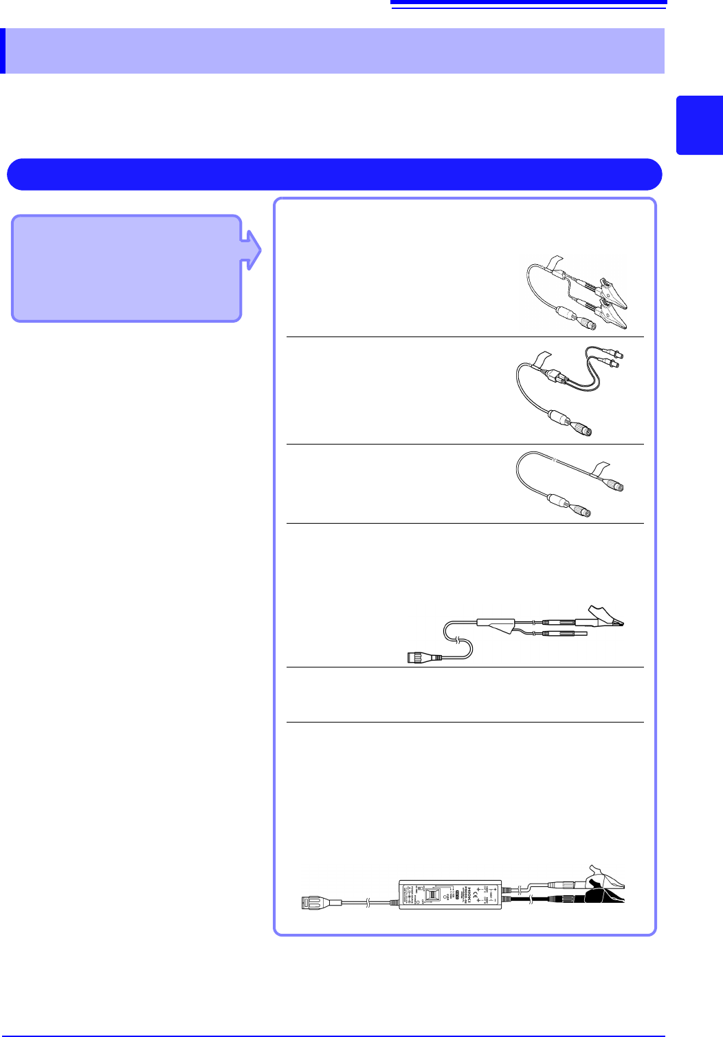
Applicable Modules
• 8966 Analog Unit
• 8968 High Resolution Unit
• 8972 DC/RMS Unit
• U8979 Charge Unit
Use to connect: Connection cords
• L9197 Connection Cord
(Maximum input voltage: 600 V)
Large alligator clip type
• L9198 Connection Cord
(Maximum input voltage: 300 V)
Small alligator clip type
• L9217 Connection Cord
(Maximum input voltage: 300 V)
For measuring BNC output
• L9790 Connection Cord
(Maximum input voltage: 600 V)
Terminal type: Alligator, contact, grabber
Example: Terminal type: Alligator
• 9166 Connection Cord
(Maximum input voltage: 30 V AC, 60 V DC)
Electrical clips
When a voltage to be measured exceeds a maximum input rating
of a module being used
• Model 9322 Differential Probe
*1
• Model 9665 10:1 Probe
• Model 9666 100:1 Probe
• Model P9000-01/-02 Differential Probe
*2
Example: Model P9000-02 Differential Probe
Measuring Voltage
Connect to the BNC jack on a module.
*1 An optional power cord or AC adapter is
required.
*2 An optional AC adapter or a commercially
available USB cable is required.
2.2 Connecting Cords
40
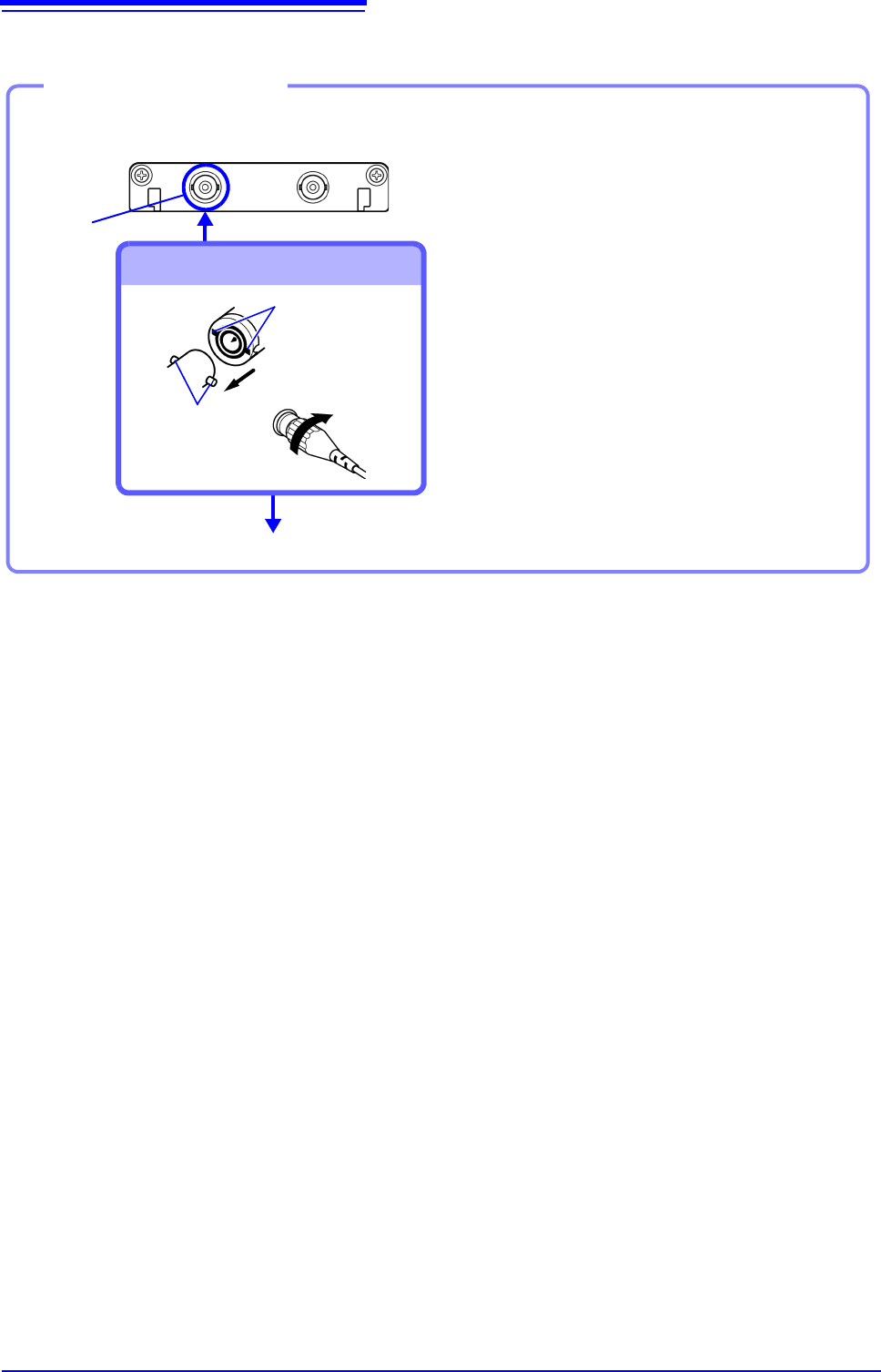
Example: 8966 Analog Unit
Required item: One of the above cables
BNC jack
Connect to BNC jack
Lock
Bayonet rugs on
the module
BNC plug slots
Connect to the measurement object
Connecting the cable
1
Connect the BNC plug on the cable to
a BNC jack on the module.
2
Align the slots in the BNC plug with
the guide pins on the jack on the mod-
ule, then push and twist the plug
clockwise until it locks.
3
Connect the cable clips to the mea-
surement object.
Disconnecting BNC connectors
Push the BNC plug, twist it counter-
clockwise, and pull it out.