MR8740、MR8741_user_manual_eng_20191016H.pdf - 第382页
17.6 Specifications of Modules 370 10250-52A2PL: Sumitomo 3M products (SCSI-2 con nec tor), (Centronics half-pitch 50 pins socket- contact) Recommended connection cable: KB-SHH2: Sa n wa Supply (SCSI-2 connector) (Centro…

17.6 Specifications of Modules
369
Chapter 17 Specifications
16
17
General Specifications
Pulse Output Specifications
Pattern Output Specifications
17.6.14 MR8791 Pulse Generator Unit
Temperature and humidity for
guaranteed accuracy
23°C±5°C (73°F±9°F), 80% RH or less (no condensation) (When installed in the Memory
HiCorder)
Guaranteed accuracy period 1 year
Product warranty period 3 years
Operating temperature and
humidity
As per Memory HiCorder in which Model MR8791 is installed
Operating environment As per Memory HiCorder in which Model MR8791 is installed
Storage temperature and
humidity
-20°C to 50°C (-4°F to 122°F), 90% RH or less (no condensation)
Maximum rated voltage to
earth
33 V AC rms or 70 V DC (between output channels and enclosure)
Anticipated transient overvoltage: 330 V
Dimensions Approx. 106W ×19.8H × 196.5D mm (4.17”W × 0.78”H × 7.74”D) (excluding protrusions)
Mass Approx. 230 g (8.1 oz.)
Number of output channels 8 (output channels and enclosure isolated; output units isolated)
(channels not isolated from each other [common GND]) (channels not isolated from output
connector frame [common GND])
Output mode 1 Pattern output/pulse output (switched for all 8 channels at once)
Output mode 2
Logic output:
Open collector Output:
Logic output/open-collector output (set separately for each of 8 channels)
Output voltage level: 0 V to 5 V (high level 3.8 V or greater, low level 0.8 V or less)
Rated current: ±5 mA
Collector/emitter absolute maximum rated voltage: 50 V
Over-current protection: 100 mA
Output mode 3 Output/open (= self-test) (switched for all 8 channels at once)
Open-collector output defini-
tion
(rising time [10% to 90%])
5 s (max.) (load capacity of 1000 pF, pull-up resistance of 1 k)
Self-test function Detected voltages: High level 3.4 V or greater, low level 1.6 V or less
Relay switching time 5 ms or less (logic/open collector switching, output/open [self-test] switching)
Standards Safety EN61010
EMC EN61326 Class A
Output frequency Setting range: 0 Hz to 20 kHz (set separately for each of 8 channels)
Setting resolution: 0.1 Hz
Frequency accuracy: ±100 ppm
Duty ratio Setting range: 0.1% to 99.9%, 0, 100% (DC)
Setting resolution: 0.1%
Duty ratio accuracy: {±100 ppm (setting period) ±150 ns} of setting
Priority to the “Minimum pulse width”and “Open collector output regula-
tion” specifications
Minimum pulse width 1 s
Clock frequency Range: 0 Hz to 120 kHz (Common for 8 channels)
Setting resolution: 10 Hz
Frequency accuracy: ±100 ppm of setting
Memory (Pattern) 2,048 words (16,384 bits = 2,048 words × 8 bits/word)
17.6 Specifications of Modules
370
10250-52A2PL: Sumitomo 3M products (SCSI-2 connector), (Centronics half-pitch 50 pins socket-
contact)
Recommended connection cable: KB-SHH2: Sanwa Supply (SCSI-2 connector) (Centron-
ics half 50-pin male)
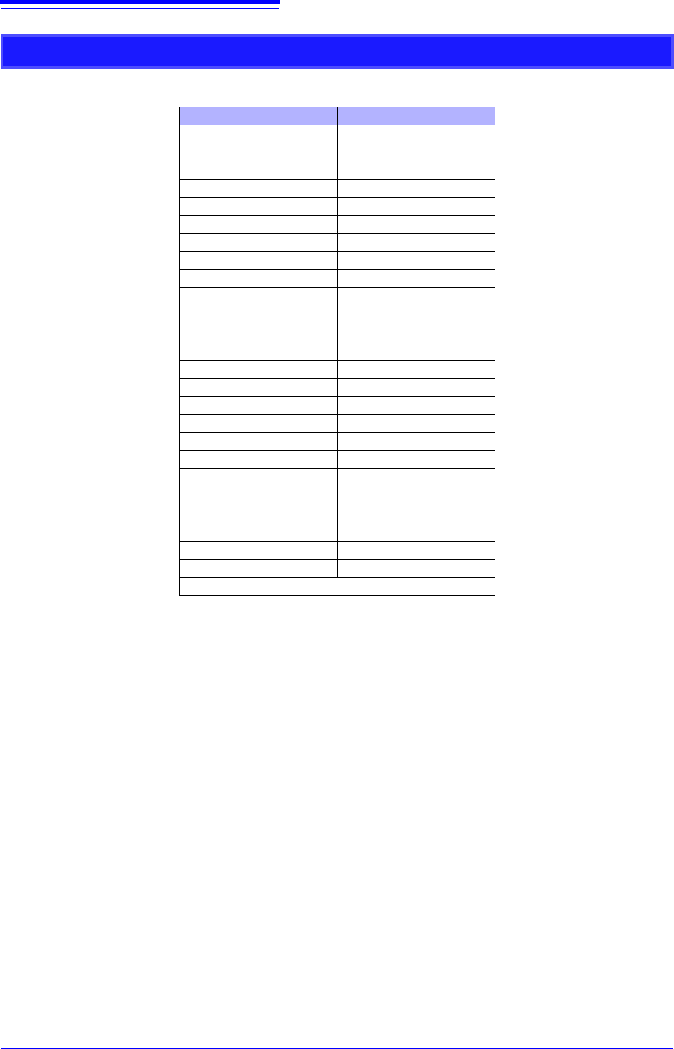
Output Connector Specifications
Pin Signal name Pin Signal name
1 I_GND 26 I_GND
2 CH1 7 I_GND
3 CH2 28 I_GND
4 CH3 29 I_GND
5 CH4 30 I_GND
6 I_GND 31 I_GND
7 CH5 32 I_GND
8 CH6 33 I_GND
9 CH7 34 I_GND
10 CH8 35 I_GND
11 I_GND 36 I_GND
12 NC 37 I_GND
13 NC 38 I_GND
14 NC 39 I_GND
15 NC 40 I_GND
16 I_GND 41 I_GND
17 NC 42 I_GND
18 NC 43 I_GND
19 NC 44 I_GND
20 NC 45 I_GND
21 I_GND 46 I_GND
22 TEST2 (DIN03)I 47 I_GND
23 TEST3 (DIN02) 48 I_GND
24 NC 49 I_GND
25 NC 50 I_GND
Frame F_GND
CH1 to CH8: Pulse output
I_GND: Isolation GND (insulated GND)
F_GND: Non-Isolation GND (main instrument GND)
NC: No Connect
TESTn: Test pin DO NOT CONNECT
371
Chapter 18 Maintenance and Service
14
18
Transporting
Pack the instrument so that it will not sustain damage during shipping, and
include a description of existing damage. We cannot accept responsibility for
damage incurred during shipping.
Use the original packing materials when transporting the instrument, if possible.
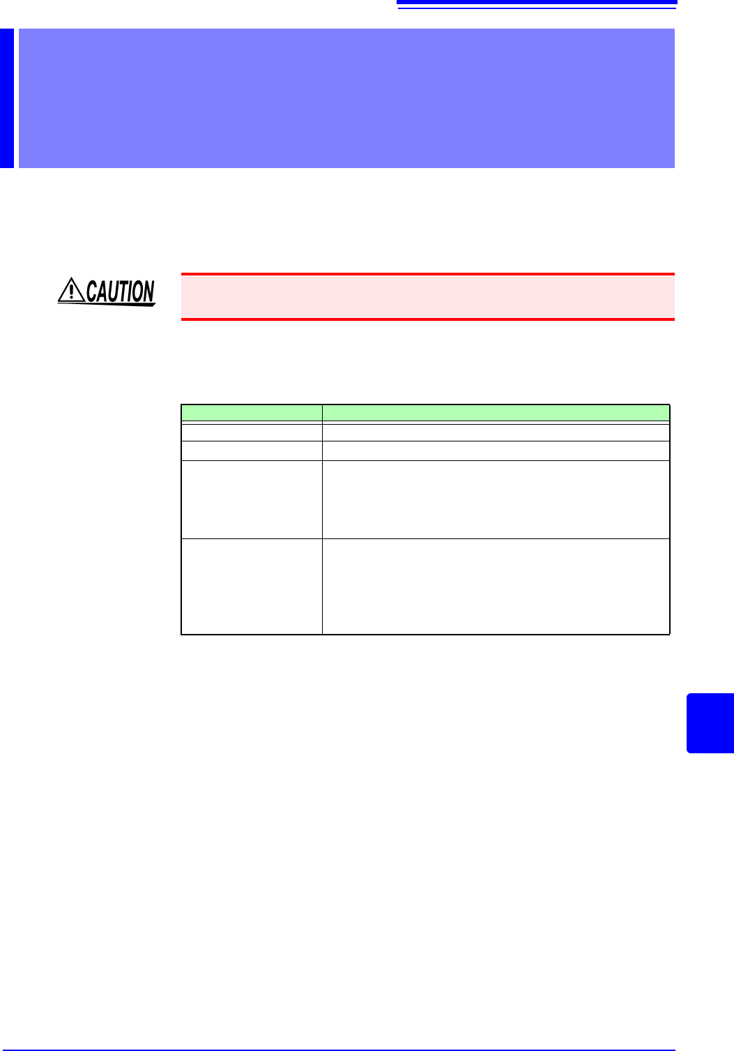
Replaceable Parts
Certain parts require replacement periodically and at the end of their useful life:
(Useful life depends on the operating environment and frequency of use. Opera-
tion cannot be guaranteed beyond the following periods)
The fuse is housed in the power unit of the instrument. If the power does not turn
on, the fuse may be blown. If this occurs, a replacement or repair cannot be per-
formed by customers. Please contact your dealer or Hioki representative.
Maintenance and
Service Chapter 18
To avoid damage to the instrument, remove the USB memory stick before ship-
ping the instrument.
Part Life
Fan Motor
Approx. 60,000 hours
Power Source
Approx. 50,000 hours
Electrolytic
Capacitors
Approx. 45,000 hours
(The useful life of electrolytic capacitors varies greatly accord-
ing to the operating environment. In severe operating environ-
ments (40°C ambient temperature), degradation occurs in
about four years, so they should be replaced periodically.)
Lithium Battery
Approx. 10 years
This instrument contains a built-in lithium battery to back up
settings and the real-time clock. Have the battery replaced if
the date and time are found to lag substantially or if settings
are not retained when power is turned off and back on. Con-
tact your dealer or Hioki representative.