MR8740、MR8741_user_manual_eng_20191016H.pdf - 第84页
3.4 Setting Measurement Configuration 72 You can specify the format in which the input signal is shown o n the Waveform screen. With 2, 4, 8, or 16 screens, analog channels can be freely assigned to the respective g raph…
3.4 Setting Measurement Configuration
71
3
Chapter 3 Measurement Procedure
Description
Recording Length and Data Samples
Each division of the recording length consists of 100 data samples. The total
number of data samples for a specified recording length = set recording length
(divisions) × 100 + 1.
However, if MR8990 Digital Voltmeter Unit is installed, the number of data sam-
ples is as follows.
• When only MR8990 is installed
Number of data samples for each division: 50 data samples
Total number of data samples for recording length: Set recording length (divi-
sions) × 50 + 1
• When a mix of MR8990 and another units is installed
Channel of MR8990
Number of data samples for each division: 50 data samples
Total number of data samples for recording length: Set recording length (divi
sions) × 50 + 1
Channel of other units
Number of data samples for each division: 100 data samples
Total number of data samples for recording length: Set recording length (divi-
sions) × 100 + 2
• Each recording length division = 100 pairs of data points, with each pair com-
posed of two values: the maximum and minimum measured values within
each sampling period. The resolution of the data measured by the recorder
function is 16bit.
When recording length is set to [Cont.]
• Data for up to 80,000 divisions from the end of measurement can be recorded
in the internal memory of the unit.
The instrument stores the maximum recording length of data back from the
point at which measurement was stopped in its internal memory (80,000 divi-
sions).
• When Auto-saving is On, the saving is not performed during the measure-
ment. At the forced shutdown point, the remaining data in memory will be
saved.
To change recording length while measuring
Recording length can be changed on the Waveform screen.
The measurement will restart with the newly set recording length.
3.4 Setting Measurement Configuration
72
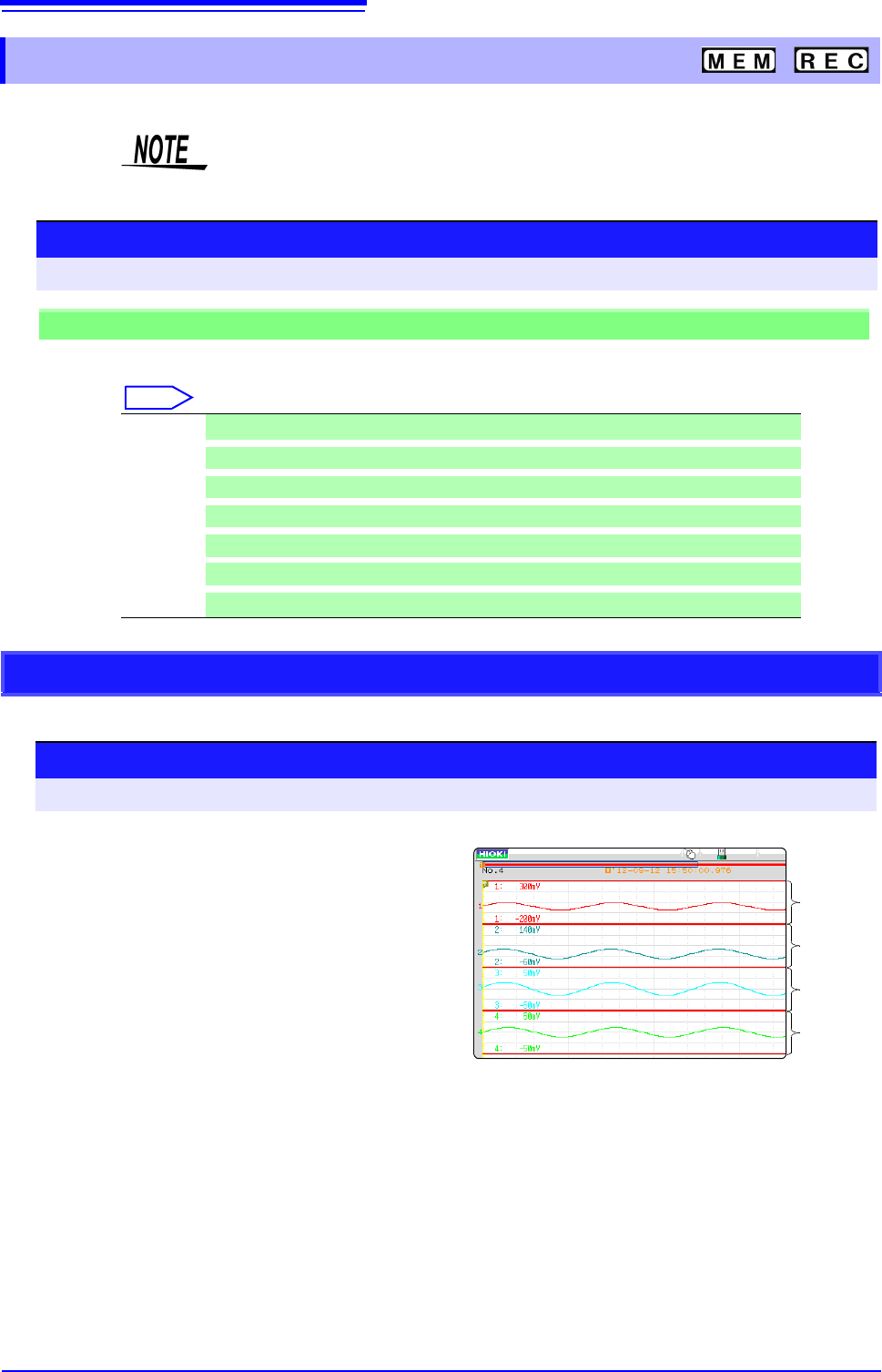
You can specify the format in which the input signal is shown on the Waveform screen.
With 2, 4, 8, or 16 screens, analog channels can be freely assigned to the respective graphs.
3.4.4 Screen Layout
Selecting X-Y1 screen or X-Y4 screen allows waveform X-Y synthesis.
(This applies to the Memory function.)
See: "6.4 Performing Waveform X-Y Synthesis" (p.127)
Procedure
To open the screen: Right-click and select [STATUS] [Status] sheet
Memory Function case
Move the flashing cursor to the [Format] item.
Select
Single Display and record using 1 graph. (default setting)
Dual
Display and record using 2 graphs.
Quad
Display and record using 4 graphs.
Oct
Display and record using 8 graphs.
Hex Display and record using 16 graphs.
XYSingle
Set input signal to X-Y and display and record the correlation using 1 graph.
XYQuad
Set input signal to X-Y and display and record the correlation using 4 graphs.
Analog Channel Assignment
Procedure
To open the screen: Right-click and select [CHAN] [Unit List] sheet
1
Move the flashing cursor to the [Graph] item.
2
Select the display screen for each channel.
The sequence is Gr1, Gr2, Gr3... from the top.
Gr1
Gr2
Gr3
Gr4
<Sample screen after setting>
3.5 Input Channel Setting
73
3
Chapter 3 Measurement Procedure
Set the analog channel and logic channel.
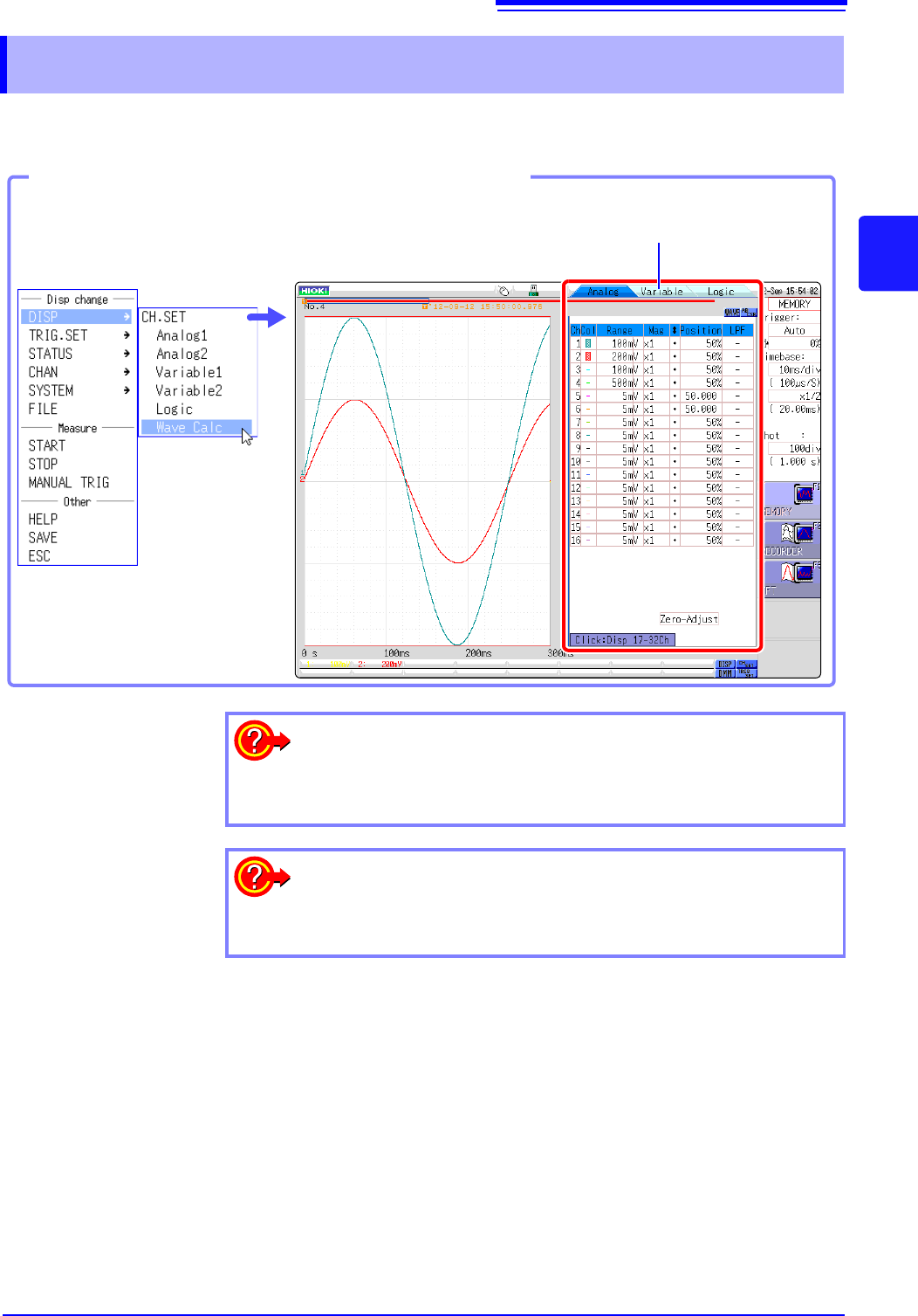
3.5 Input Channel Setting
See: "Displaying All Channels for Making the Variable Function Setting" (p.157)
Opening the Channel settings window
You can switch setting
screens by clicking a tab.
Click [DISP]→ [CH.SET] in the
right-click menu.
To hide waveform interpolation
Set the waveform display color in the channel setting window to Off.
See: "1. Waveform Display Color" (p.76)
To copy the settings of one channel to another
See: "7.8 Copying settings to other channels (calculation No.) (Copy func-
tion)" (p.160)