MR8740、MR8741_user_manual_eng_20191016H.pdf - 第90页
3.5 Input Channel Setting 78 Brackets indicate valid data range *: With the 8967 TEMP Unit, the valid range differs depending on t he thermocouple. For information on the minimum resolutio n, see the specifications of th…
3.5 Input Channel Setting
77
3
Chapter 3 Measurement Procedure
4. Vertical axis
(Voltage axis)
Zoom
Vertical axis (voltage axis) zoom-up or zoom-down settings can be made sepa-
rately for each channel. The settings will be used for display.
Zooming is carried out using the zero position as reference. The measurement
resolution does not change.
See: "6.5.3 Magnifying and Compressing Vertical Axis (Voltage Axis)" (p.131)
To achieve a user-specified zoom setting, the Variable function is used. By
reversing plus/minus, the waveform can be inverted.
See: "7.5 Variable Function (Setting the Waveform Display Freely)" (p.155)
"7.7 Inverting the Waveform (Invert Function)" (p.159)
5. Vernier Fine adjustment of input voltage can be performed arbitrarily on the Waveform
screen (display only). When recording physical values such as noise, temperature
and acceleration using sensors, amplitude can be adjusted to facilitate calibration.
See: "7.6 Fine Adjustment of Input Values (Vernier Function)" (p.158)
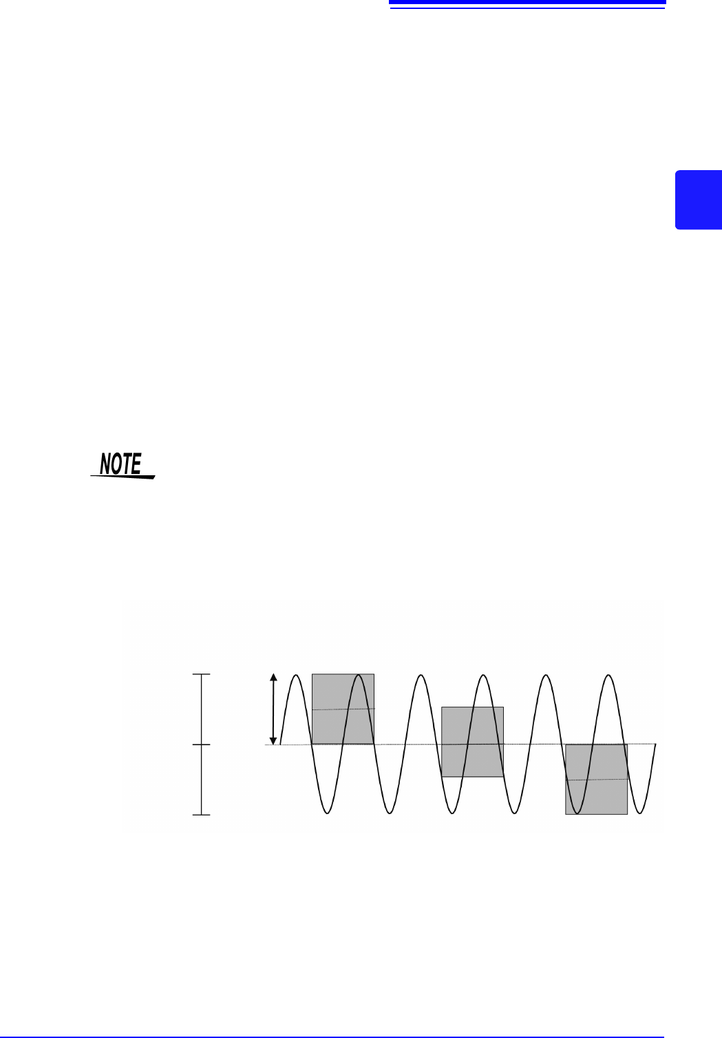
6. Zero Position Sets the 0 V level display position. If the 0 V input level has shifted, perform
zero-adjust.
See: "2.6 Adjusting the Zero Position (Zero-Adjust)" (p.58)
See: "2.7 Performing Calibration (When Mounting MR8990)" (p.59)
If the zero position of the 8969 and U8969 Strain Unit is out of alignment, perform
auto balance.
See: "7.9.4 Setting Model 8969 and U8969 Strain Unit" (p.165)
The zero position is as shown in the illustration below.
(Example: 8966 Analog Unit)
• Simply moving the display position will not apply an offset to the input.
• Zoom of the vertical axis direction (voltage axis) is based on the zero position.
• The voltage range displayed in the waveform screen changes with zero posi-
tion and zoom of the vertical axis (voltage axis) but the measurable range does
not change.
A/D Data
2047
0
-2047
A/D Data
0 V
2000 LSB
0 %
50 %
100 %
Display screen
(Zero position: 0%)
Display screen
(Zero position: 50%)
Display screen
(Zero position:100%)
<Zoom factor ×1>
3.5 Input Channel Setting
78
Brackets indicate valid data range
*: With the 8967 TEMP Unit, the valid range differs depending on the thermocouple. For information on the minimum resolution,
see the specifications of the 8967 TEMP Unit.
7. Low-pass
filtering
Make settings for the low-pass filter of the module. This is useful for eliminating
unwanted high-frequency components. The filter type depends on the module.
Make the setting according to the input characteristics.
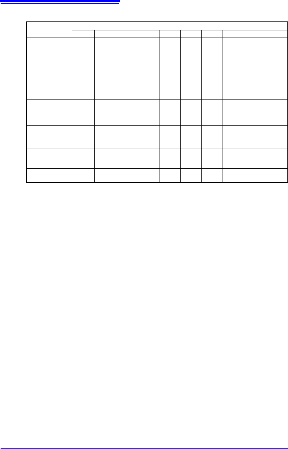
Full-scale resolution for input units at various vertical axis zoom factors (LSB)
Module Zoom factor
×1/10 ×1/5 ×1/2 ×1 ×2 ×5 ×10 ×20 ×50 ×100
8966 (Analog)
8971 (Current)
8972 (DC/RMS)
20000
(4000)
10000
(4000)
4000 2000 1000 400 200 100 40 20
8967
(Temperature)
*
200000 100000 40000 20000 10000 4000 2000 1000 400 200
8968
(High resolution)
U8974
(High voltage)
320000
(64000)
160000
(64000)
64000 32000 16000 6400 3200 1600 640 320
8969, U8969
(Strain)
U8979
(Charge)
250000
(64000)
125000
(64000)
50000 25000 12500 5000 2500 1250 500 250
8970
(Power frequency )
20000 10000 4000 2000 1000 400 200 100 40 20
8970 (Count ) 400000 200000 80000 40000 20000 8000 4000 2000 800 400
8970 (Excluding
power frequency
and count)
100000 50000 20000 10000 5000 2000 1000 500 200 100
MR8990
(DVM)
1200000 1200000
1200000 1000000
500000 200000 100000 50000 20000 10000
3.5 Input Channel Setting
79
3
Chapter 3 Measurement Procedure
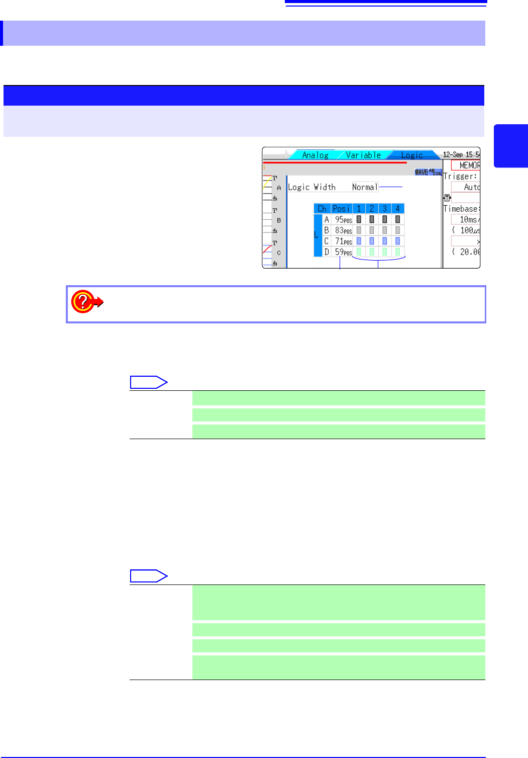
Make settings for the logic channels. The channel settings window (Logic sheet) is shown when the
display format is 1, 2, 4, 8 or 16 screens.
1. Logic Width Allows changing the display width of the logic waveform.
Making waveforms more narrow can enhance the readability of the display when
there are a high number of waveforms.
Select
2. Waveform
Display
Position
Determines where on the screen the logic waveform is displayed.
The position can be freely moved within the range of the display.
3. Waveform
Display Color
Specifies the color in which the waveform of the selected channel is displayed.
You can also select the same color as another channel.
For logic modules, the color can be specified for each module and each channel
separately.
Select
3.5.3 Logic Channel
1.
Procedure
To open the screen: Right-click and select [DISP] Waveform screen Right-click and select [CH.SET]
Channel settings window ([Logic] sheet)
2. 3.
1
Move the flashing cursor to the channel for
which to make settings.
2
Select the settings by clicking the mouse.
To copy the settings of one channel to another
See: "7.8 Copying settings to other channels (calculation No.) (Copy function)" (p.160)
Wide Make the waveform wider.
Normal Display the waveform at normal width.
Narrow
Make the waveform more narrow. (default setting)
Off The waveform is not displayed. If the [Save Channel] setting is [Disp Ch], data
for the channel will not be automatically saved.
See: "4.2.2 Automatically Saving Waveforms" (p.88)
On
The waveform is displayed. Set the display color by clicking [ ] or [ ].
Probe On-Off
Switches the waveform display of the same probes to all ON or all OFF.
All On-Off Switches the display of all logic waveforms to all ON or all OFF.
This can be selected when the cursor at in the waveform display position item.