MR8740、MR8741_user_manual_eng_20191016H.pdf - 第201页
189 7 Chapter 8 T rigger Settings 8 Triggering is the process of controlling the start and sto p of recording by specific signals or condi- tions (criteria). When recording is started or stopped by a specific signal, we …
7.11 Saving Waveforms Registered in Model U8793 onto a Storage Device
188
You can save the arbitrary waveform data registered in U8793 in the media.
For saving methods, refer to "4.2.5 Save Waveform Output Data to the Media" (p.98).
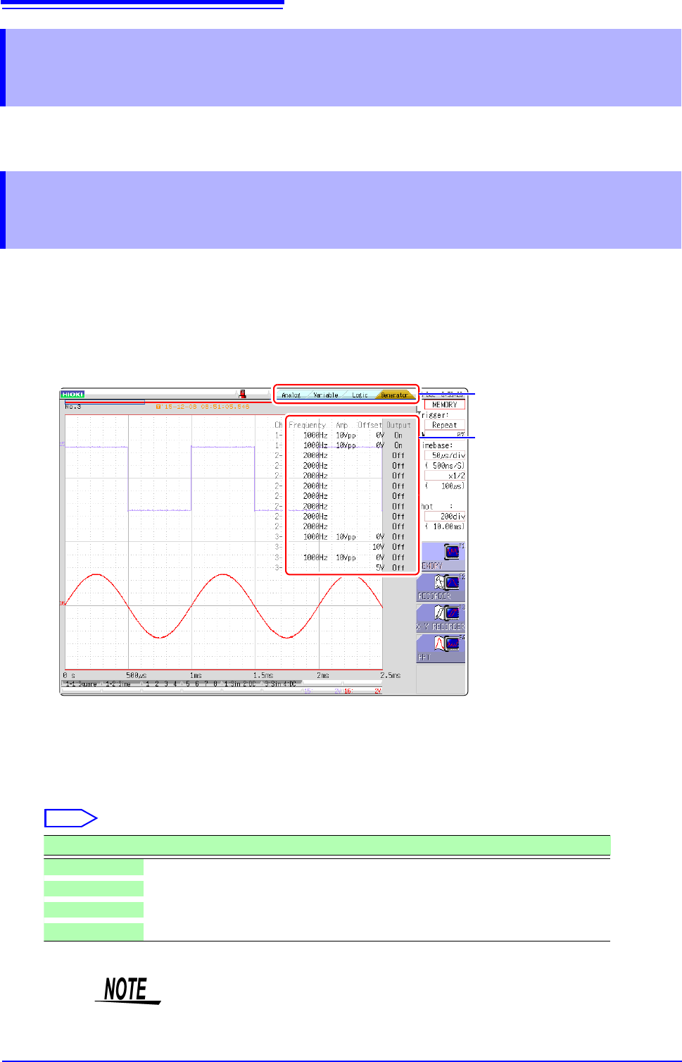
Parameters (frequency, amplitude, and offset) for the output waveform that was configured on the Generator
screen (signal generation setting screen) can be changed on the Waveform screen.
The ability to configure and change these settings while outputting and measuring the resulting waveform pro-
vides a convenient way to measure a waveform while varying its parameters.
7.11 Saving Waveforms Registered in Model
U8793 onto a Storage Device
7.12 Setting Output Waveform Parameters on the
Waveform Screen
1
Display the Waveform screen (if viewing another screen, press DISP to display the Waveform
screen).
2
Press CH.SET (to display the tabs).
3
Press CH.SET or select the [Generator] tab with the mouse.
4
Set the following parameters as desired.
3
4
Select
Selections Description
Frequency Sets the frequency.
Amp Sets the amplitude.
Offset Sets the offset.
Output Turns output on or off.
For details, see the instruction manual of Models U8793, MR8790, and MR8791.
189
7
Chapter 8 Trigger Settings
8
Triggering is the process of controlling the start and stop of recording by specific signals or condi-
tions (criteria). When recording is started or stopped by a specific signal, we say the trigger is
"applied" or "triggering occurs".
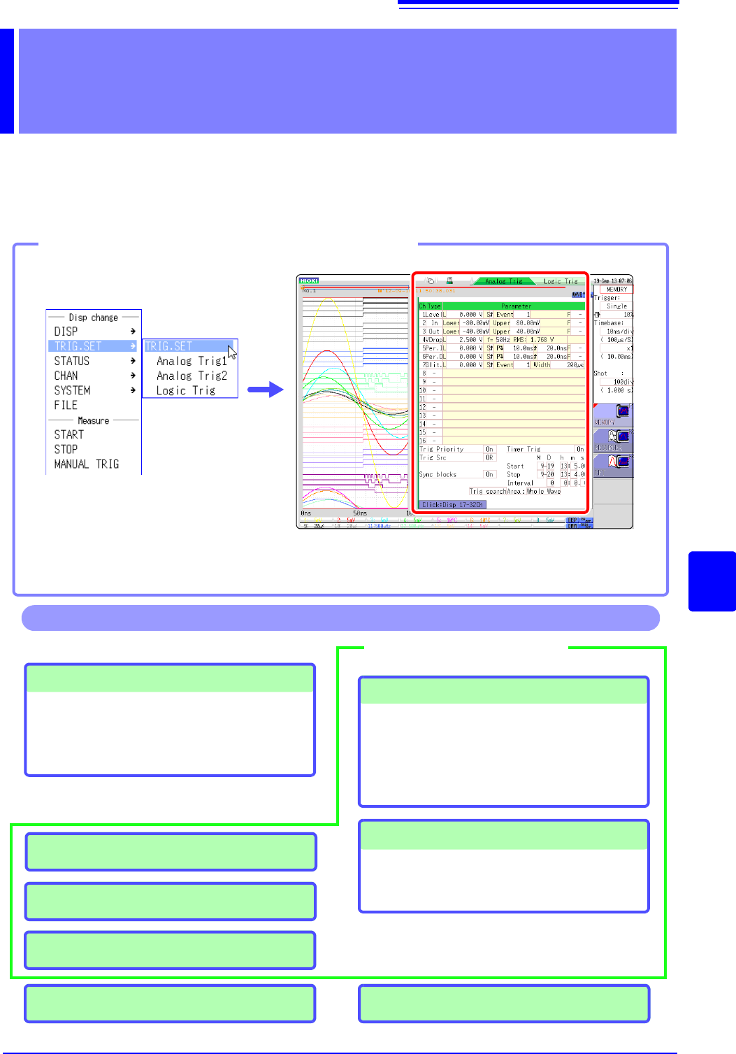
Trigger settings are made in the Trigger settings window of the Waveform screen.
Trigger Settings Chapter 8
Opening theTrigger settings window
Click [TRIG.SET] in the right-
click menu.
If the trigger setting screen is hard to see due to waveform overlap, narrow the wave-
form display width to divide the waveform display screen and trigger settings screen.
Refer to "6.7.3 Switching the Waveform Display Width" (p.135).
Trigger Settings
• Trigger mode setting (p.191)
• Combining logic (AND/OR) for multiple trigger
sources (p.208)
• Pre-trigger settings (p.204)
Analog Trigger Settings (p.192)
• Level trigger
• Window trigger
• Period trigger
• Glitch trigger
• Slope trigger
Logic Trigger Settings (p.197)
• Setting combining logic for logic triggers
• Trigger filter settings
• Trigger pattern settings
Manual Trigger Settings (p.203)
Trigger Source Settings
Trigger Output (MR8741) (p.341)
Operations available from the Trigger settings window
External Trigger Settings (p.203)
Timer Trigger Settings (p.199)
Searching for trigger positions (p.209)
8.1 Setting Workflow
190
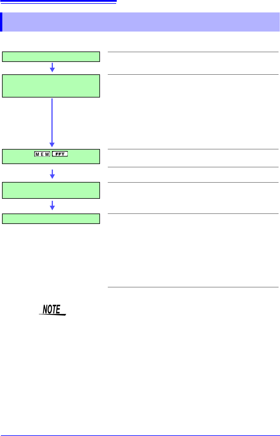
The procedure for making trigger settings is as follows.
8.1 Setting Workflow
Trigger Mode Settings
Set whether to continue to accept triggers after measuring. (p.191)
Trigger Type Settings
Make trigger source-related settings.
• Analog trigger
• Logic trigger
• Timer trigger
• External trigger
• Manual trigger
(p.192)
(p.197)
(p.199)
(p.203)
(p.203)
Pre-Trigger Settings
Set the amount to record before and after a trigger point.
(p.204)
Setting AND/OR Between Trigger
Sources
Select AND/OR logical combination of analog, logic, external
and timer triggers to be applied.
(p.208)
Start Measurement
Click [START] in the right-click menu to start measuring.
(However, operation differs according to the setting for Start Action
(p.311).)
Data acquisition starts when trigger criteria are met.
To stop measurement: Click [STOP] in the right-click menu.
Click once: recording stops at the end of the specified recording length.
Click twice: recording stops immediately.
Available settings for the respective items depend on the function.
• Except for manual trigger, triggering is based on the AND/OR combination of
trigger sources. (p.208)
• When triggering occurs, the TRIG OUT terminal for control of external devices
carries an output signal. (p.341) (MR8741 only)
• Settings for the analog trigger are restricted for the channel of the MR8990
Digital Voltmeter Unit.
• When MR8990 Digital Voltmeter Unit is installed, the trigger position may be
offset by 1 point.