MR8740、MR8741_user_manual_eng_20191016H.pdf - 第383页
371 Chapter 18 Maintenance and Service 14 18 T ransporting Pack the instrument so that it will no t sustain damage during shipping, and include a description of existing damage . We cannot accept responsibility for damag…
17.6 Specifications of Modules
370
10250-52A2PL: Sumitomo 3M products (SCSI-2 connector), (Centronics half-pitch 50 pins socket-
contact)
Recommended connection cable: KB-SHH2: Sanwa Supply (SCSI-2 connector) (Centron-
ics half 50-pin male)
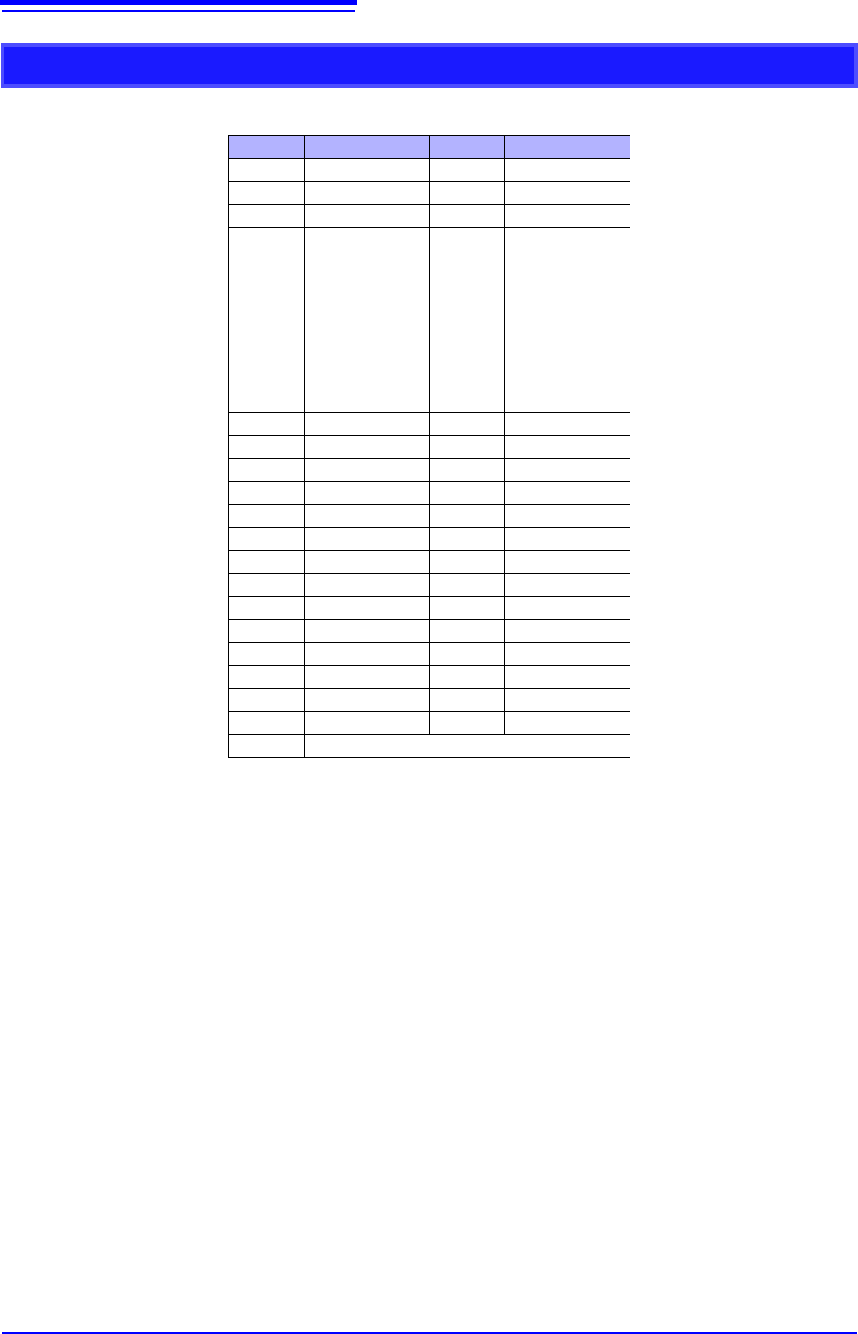
Output Connector Specifications
Pin Signal name Pin Signal name
1 I_GND 26 I_GND
2 CH1 7 I_GND
3 CH2 28 I_GND
4 CH3 29 I_GND
5 CH4 30 I_GND
6 I_GND 31 I_GND
7 CH5 32 I_GND
8 CH6 33 I_GND
9 CH7 34 I_GND
10 CH8 35 I_GND
11 I_GND 36 I_GND
12 NC 37 I_GND
13 NC 38 I_GND
14 NC 39 I_GND
15 NC 40 I_GND
16 I_GND 41 I_GND
17 NC 42 I_GND
18 NC 43 I_GND
19 NC 44 I_GND
20 NC 45 I_GND
21 I_GND 46 I_GND
22 TEST2 (DIN03)I 47 I_GND
23 TEST3 (DIN02) 48 I_GND
24 NC 49 I_GND
25 NC 50 I_GND
Frame F_GND
CH1 to CH8: Pulse output
I_GND: Isolation GND (insulated GND)
F_GND: Non-Isolation GND (main instrument GND)
NC: No Connect
TESTn: Test pin DO NOT CONNECT
371
Chapter 18 Maintenance and Service
14
18
Transporting
Pack the instrument so that it will not sustain damage during shipping, and
include a description of existing damage. We cannot accept responsibility for
damage incurred during shipping.
Use the original packing materials when transporting the instrument, if possible.
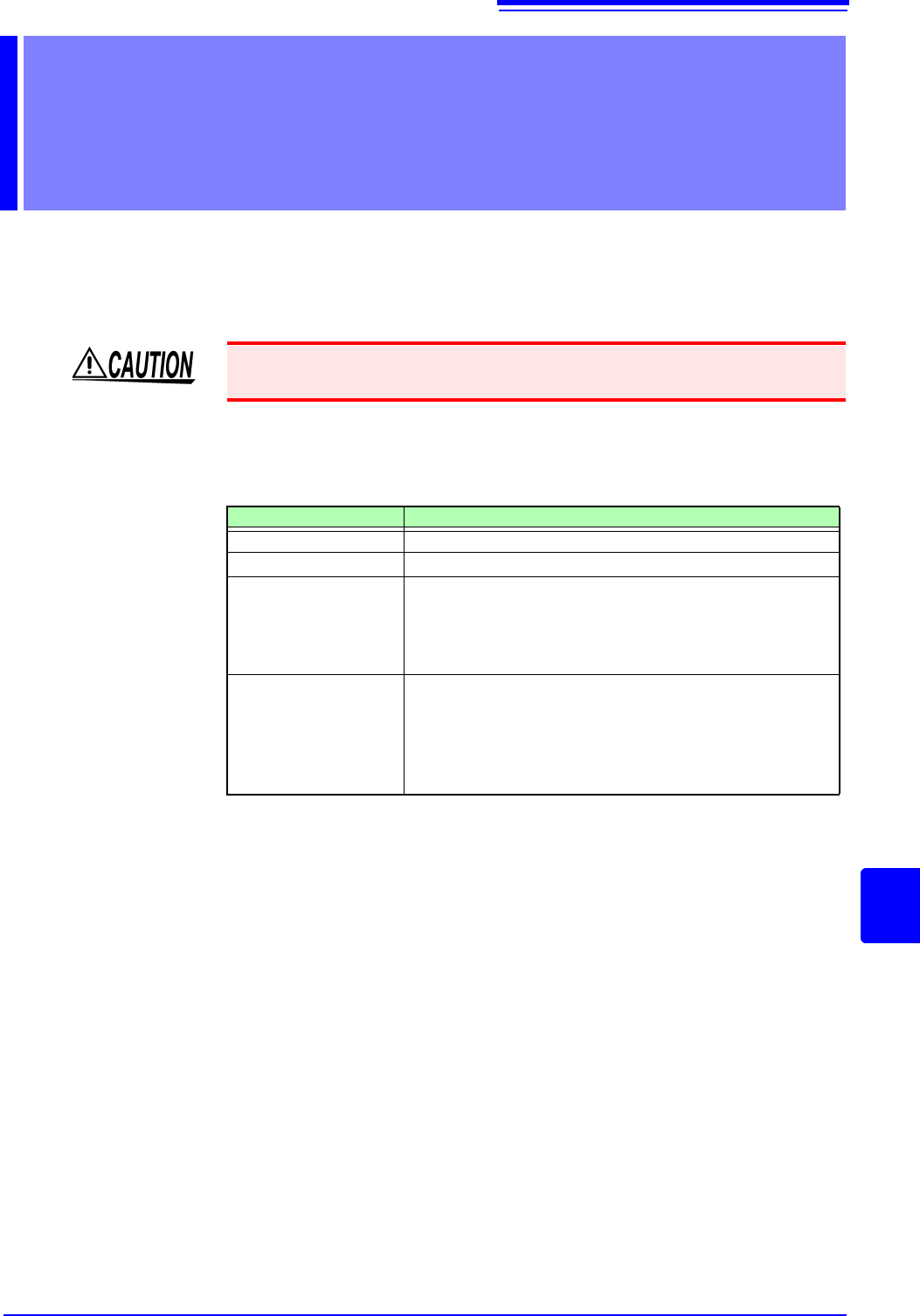
Replaceable Parts
Certain parts require replacement periodically and at the end of their useful life:
(Useful life depends on the operating environment and frequency of use. Opera-
tion cannot be guaranteed beyond the following periods)
The fuse is housed in the power unit of the instrument. If the power does not turn
on, the fuse may be blown. If this occurs, a replacement or repair cannot be per-
formed by customers. Please contact your dealer or Hioki representative.
Maintenance and
Service Chapter 18
To avoid damage to the instrument, remove the USB memory stick before ship-
ping the instrument.
Part Life
Fan Motor
Approx. 60,000 hours
Power Source
Approx. 50,000 hours
Electrolytic
Capacitors
Approx. 45,000 hours
(The useful life of electrolytic capacitors varies greatly accord-
ing to the operating environment. In severe operating environ-
ments (40°C ambient temperature), degradation occurs in
about four years, so they should be replaced periodically.)
Lithium Battery
Approx. 10 years
This instrument contains a built-in lithium battery to back up
settings and the real-time clock. Have the battery replaced if
the date and time are found to lag substantially or if settings
are not retained when power is turned off and back on. Con-
tact your dealer or Hioki representative.

18.1 Trouble Shooting
372
18.1 Trouble Shooting
If damage is suspected, check the "Troubleshooting" section before
contacting your dealer or Hioki representative.
If Power and Operating Mouse Malfunction
Symptom Check Item, or Cause Remedy and Reference
The display does not
appear when you turn the
power on.
Is the power cord disconnected?
Are connections made correctly?
Verify that the power cord is connected
properly.
"2.4 Supplying Power" (p.55)
Cannot operate the instru-
ment with a mouse.
• Is the USB mouse connected?
• Are you using a hub or special
mouse?
• Is there a source of interference
nearby?
• Check the USB connector.
• If you are using a hub, connect the
mouse directly to the instrument.
Use an ordinary mouse.
• Move the mouse away from the source
of interference.
If the Display or Operations Malfunction
Symptom Check Item, or Cause Remedy and Reference
Data is not displayed on
an external LCD monitor.
• Is it connected properly?
• Is it a digital LCD monitor?
• Are you using a VGA-DVI adapter
cable?
• Check the connections and power of the
instrument and LCD monitor.
• An analog monitor (VGA output) cannot
be used. Use an LCD monitor with a DVI-
D (digital output) connector.
The monitor flickers.
• Is there a source of interference
nearby?
• Are you using a special LCD moni-
tor? (Although extremely uncom-
mon, flickering may be caused by
incompatibility with the LCD monitor.)
• Move the cable away from the source of
interference.
• Use an ordinary LCD monitor.
A waveform does not
appear when measure-
ment is started
• Is the “Pre-Trigger wait” message
displayed?
• Is the "Trigger wait" message dis-
played?
When pre-triggering is enabled, triggering is
ignored until the pre-trigger portion of the
waveform has been acquired. Recording
starts when a trigger occurs.
No changes occur in the
displayed waveform.
• Is the clamp sensor or connection
cable connected correctly?
• Is the vertical axis (voltage axis)
range set properly?
• Is the low-pass filter enabled?
Verify that the clamp sensor or connection
cable is connected correctly.
Verify the input channel settings.
While measuring with the
memory function, the dis-
played frequency is much
lower than the actual fre-
quency.
Aliasing may be occurring.
Change the timebase to use a faster sam-
pling rate.
"3.4.2 Time Axis Range and Sampling
Rate" (p.67)