MR8740、MR8741_user_manual_eng_20191016H.pdf - 第233页
9.4 Saving Numerical Calculation Results 221 Chapter 9 Numerical Calculat ion Functions 8 9 Calculate and automatically save during data ac quisition. Before me asurement begins, the calcula- tion settings need to be set…
9.3 Judging Calculation Results
220
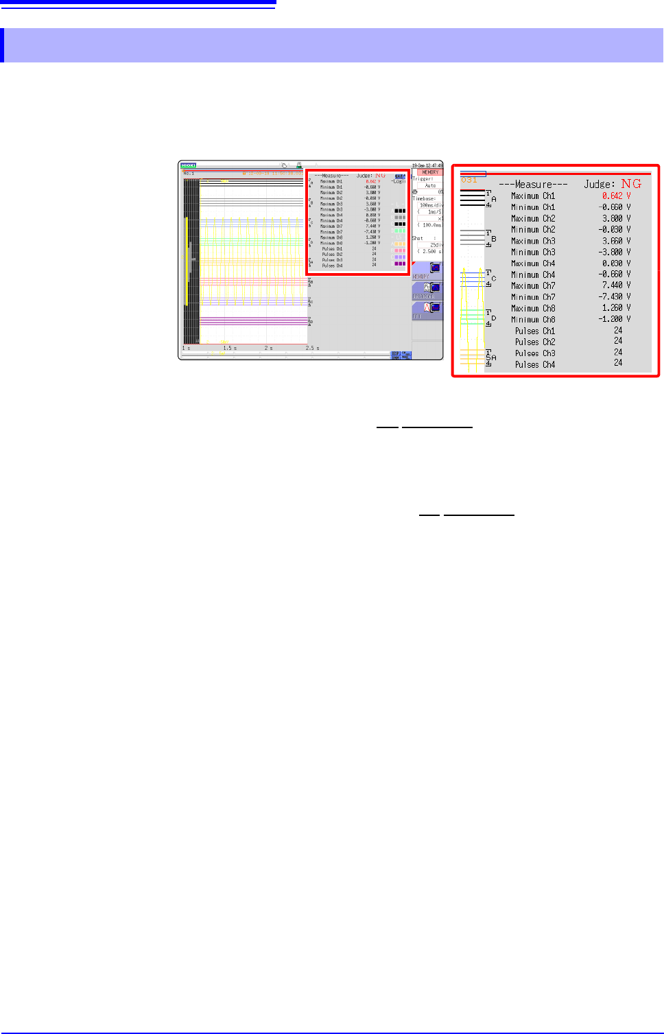
Judgment results of numerical calculations are displayed on the Waveform screen.
Within the judgment threshold range: GO judgment
Out of the judgment threshold range: NG judgment (displayed in red)
When the judgment result is GO
• The GO signal is output at the GO
/EXT.OUT.1 external I/O terminal. (MR8741
only)
When the judgment result is NG
• The NG signal is output at the NG
/EXT.OUT.2 external I/O terminal.
(MR8741 only) The NG judgment is asserted when any channel is judged as
NG.
• When the beeper is enabled, a beep sounds when a result is out of the thresh-
old range.
9.3.1 Display of Judgment Results and Signal Output
9.4 Saving Numerical Calculation Results
221
Chapter 9 Numerical Calculation Functions
8
9
Calculate and automatically save during data acquisition. Before measurement begins, the calcula-
tion settings need to be set.
9.4 Saving Numerical Calculation Results
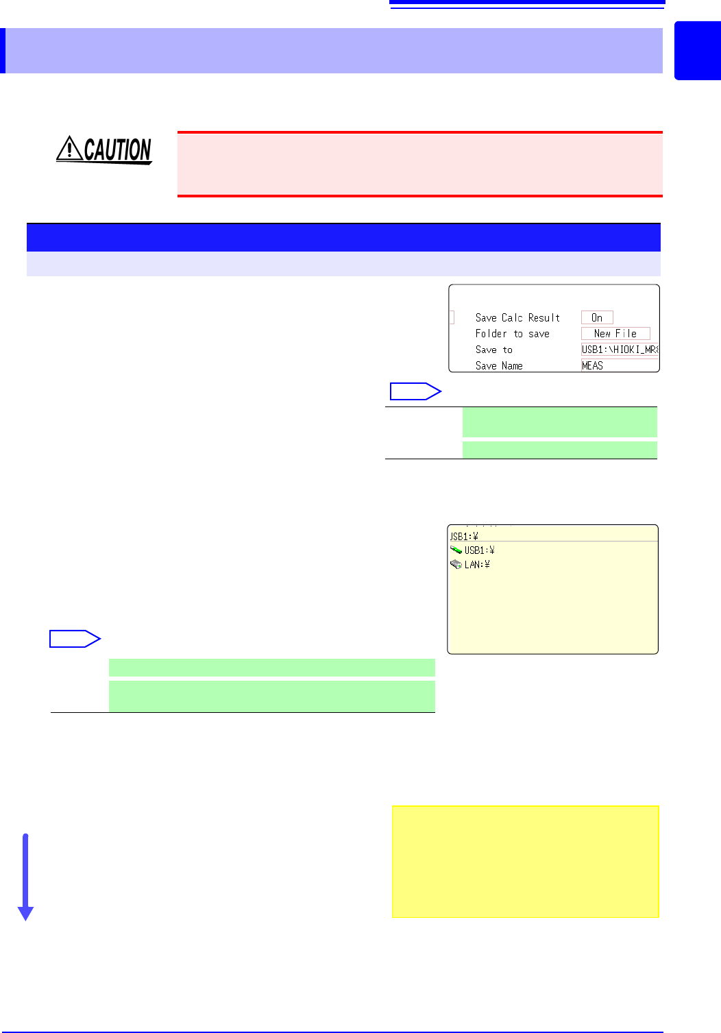
When using auto save during measurement, do not remove the storage media
specified as the save destination until the measurement operation is completely
finished. Doing so may damage data on the storage media.
Procedure
To open the screen: Right-click and select [STATUS] [Num Calc] sheet
1
Enable the saving of numerical calculation results.
Move the flashing cursor to the [Save Calc Result]
item.
Select [On]. (default setting: Off)
2
Select the file creation method.
Select
Move the flashing cursor to the [Folder to save] item.
3
Set the save target
Move the flashing cursor to the [Save To] item.
Select [Edit].
The Browse folders dialog box appears. (See illustration at right.)
Move the flashing cursor to the save target media.
Select [Confirm] to confirm the selection.
Select
To create a new folder to use as target, select [New
Folder]. When [LAN] is set as the save destination,
[New Folder]
setting is ignored and the folder named
with the current date is created.
4
Enter a save name (if you want to use a different
name).
Move the flashing cursor to the [Save Name] item.
Enter the save name. (default setting: MEAS)
See: "7.1 Adding Comments" (p.138)
When [LAN] is set as the save destination, [Save
Name] setting is ignored and the files to be saved are
named in the previously-determined format.
See:
"Save Operations (When setting the save destination to [LAN])" (
p.92)
Confirm the measurement configuration and numerical
calculation result settings, then start measurement.
New File Creates a new file for each measure-
ment.
Existing File
Adds calculation results to one file.
USB1 Automatically save the waveform data on the USB memory stick.
LAN
Automatically save the waveform data on the PC connected via
LAN. Model 9333 LAN Communicator is required to be installed.
1
2
3
4
Save Name
• The maximum length of the Save Name string
is 123 characters. The maximum path length is
255 characters.
• A sequential number starting from 0001 is auto-
matically appended to the Save Name (when
[New File] is selected).
9.4 Saving Numerical Calculation Results
222
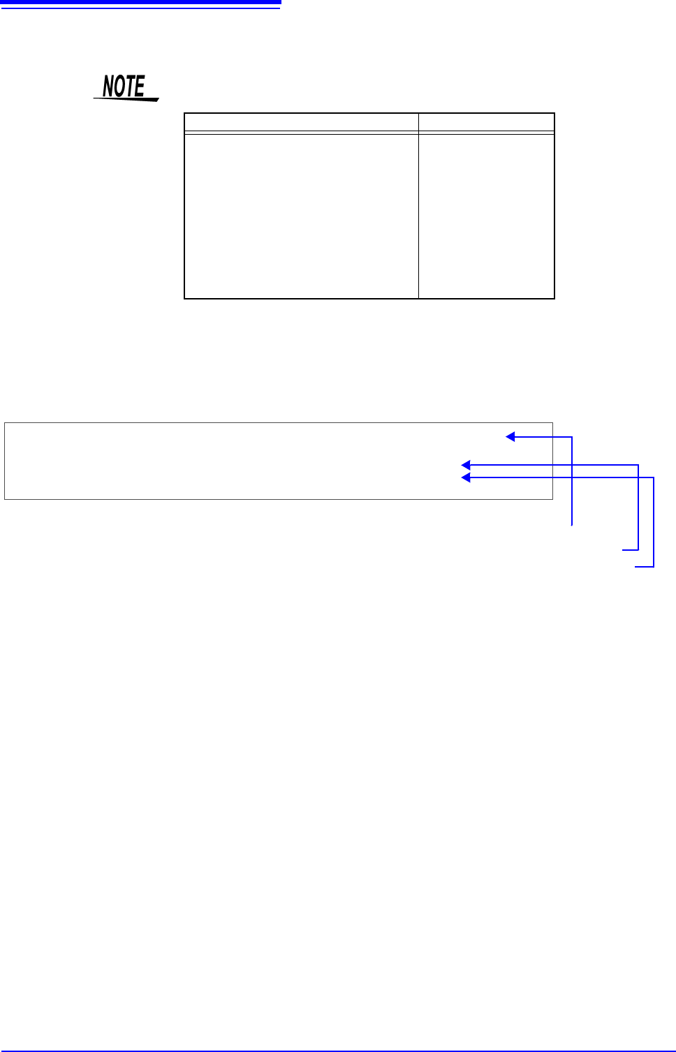
Example for saving numerical calculation results ___________________
If you save numerical calculation results, characters or display items used on the
instrument are converted as shown below.
Characters used on the instrument Saved characters
2
^2
3
^3
~u
~o
e~e
°~c
±~+
(display only)
uE
°C (
display only)
C
"Trig Time" ,"No1 Maximum Ch1" ,"No2 Minimum Ch1" ,"No3 Maximum Ch2" ,"No4 Minimum Ch2"
"","V","V","V","V"
"08-04-11 17:40:33.351","+3.00078E-05","+2.12000E-04","+2.00000E-03","+1.30000E-03"
"08-04-11 17:44:25.976","+3.06078E-05","+2.39996E-04","+2.00000E-03","+1.10000E-03"
<When calculation settings are as follows>
Calculation No. 1: Maximum value of analog channel 1
Calculation No. 2: Maximum value of analog channel 1
Calculation No. 3: Maximum value of analog channel 2
Calculation No. 4: Maximum value of analog channel 2
Line 1: Calculation Settings
Line 2: Calculation Result Unit
From Line 3: Calculation Results
Recorded in the order of the calculation settings of line 1.