MR8740、MR8741_user_manual_eng_20191016H.pdf - 第55页
2.2 Connecting Cords 43 2 Chapter 2 Measurement Prep arations Applicable Modules • Model U8969 S train Unit • Model 8969 S train Unit The following device can be connected to the modu le. • S train Gauge Transducer (Not …
2.2 Connecting Cords
42
Applicable Modules
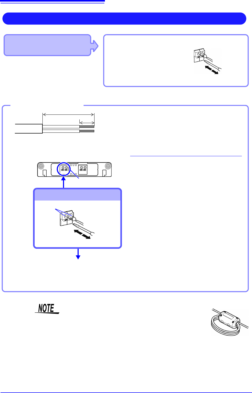
• 8967 TEMP Unit
Use to connect: Thermocouple
(Compatible wire: AWG 16 to 26, 0.4
to 1.2 mm diameter)
Connect to terminal block
Measuring Temperature
Connect to the terminal block on the input
module.
Terminal Block
Connection Holes
Insert to terminal block
Outer Insulation
10 mm
25 mm
Thermocouple
single wires
Inner insulation
Attach to the measurement object
Inserting a Thermocouple
2
1
3
4
5
1
Strip insulation from the thermocouple
wires as shown at the left.
Stripping length: approx. 10 mm
2
Push the blade of a flat screwdriver
into the button on the terminal block of
the module.
3
Insert each thermocouple wire into the
appropriate terminal hole while press-
ing the button.
Confirm proper polarity.
4
Release the button.
The thermocouple is connected.
5
Attach to the measurement object.
To remove the thermocouple
Hold the button while pulling the ther-
mocouple wire out.
Required item:
Thermocouple, Ferrite clamp-on choke (8967’s option),
flat-blade screwdriver (2.6-mm blade)
Recommended wire:
Compatible wire:Single-strand thermocouple wire, 0.4
to 1.2-mm diameter
Stripping length:10 mm
If surrounding equipment is affected by noise, coil the ther-
mocouple several times and then attach the included ferrite
clamp-on choke (as seen in the diagram to the right).
2.2 Connecting Cords
43
2
Chapter 2 Measurement Preparations
Applicable Modules
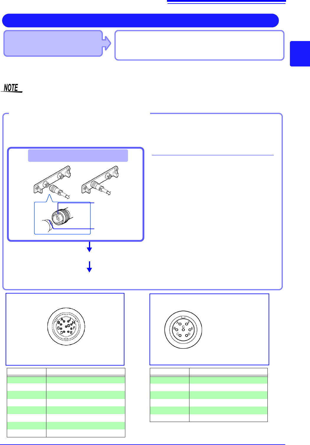
• Model U8969 Strain Unit
• Model 8969 Strain Unit
The following device can be connected to the module.
• Strain Gauge Transducer (Not available from Hioki)
• Connect L9769 or 9769 Conversion Cable to the strain gauge
Measuring vibration or displacement with a strain gauge transducer
Connect a strain gauge transducer to a connector on Model U8969 Strain Unit via Model L9769 Conversion Cable; Mod-
el 8969 Strain Unit via Model 9769 Conversion Cable.
The instrument describes Model U8969 as “8969”.
Connect the strain gauge transducer to a
measurement object.
Connecting the L9769
1
Insert Model L9769 into a connector of
Model U8969 with the slot of the plug
aligned with the outward indentation of
the connector.
2
Insert the plug into the connector until
they are locked together.
3
Connect Model L9769 to the strain
gauge transducer.
4
Connect the strain gauge transducer to
a measurement object.
Example: Connecting the strain gauge transducer to Model U8969 Strain Unit via Model L9769 Con-
version Cable
Required items:
Model L9769 Conversion Cable, strain gauge trans-
ducer
Connect to module's terminal
Connect Model L9769 to the strain gauge
transducer.
Applied voltage: bridge
voltage of 2 V
Connector Pinout of the L9769 Conversion
Cable on strain gauge transducer side
4
3
1
The metal shell is connected to the GND
of the instrument.
Connector Pinout of the U8969
Pin Mark Description
A BRIDGE+
B INPUT+
C BRIDGE-
D INPUT+
E FLOATING COMMON
F SENSE+
G SENSE-
H, J N.C.
Pin Mark Description
A BRIDGE+, SENSE+
BINPUT-
C BRIDGE-, SENSE-
DINPUT+
E FLOATING COMMON
F, G N.C.
The metal shell is connected to the GND
of the instrument.
How to disconnect Model L9769
Pull the sleeve of the plug gently, releasing the
plug, and disconnect the cable.
2
Plug’s slot
Connector’s inden-
tation
2.2 Connecting Cords
44
Attach to the measurement object
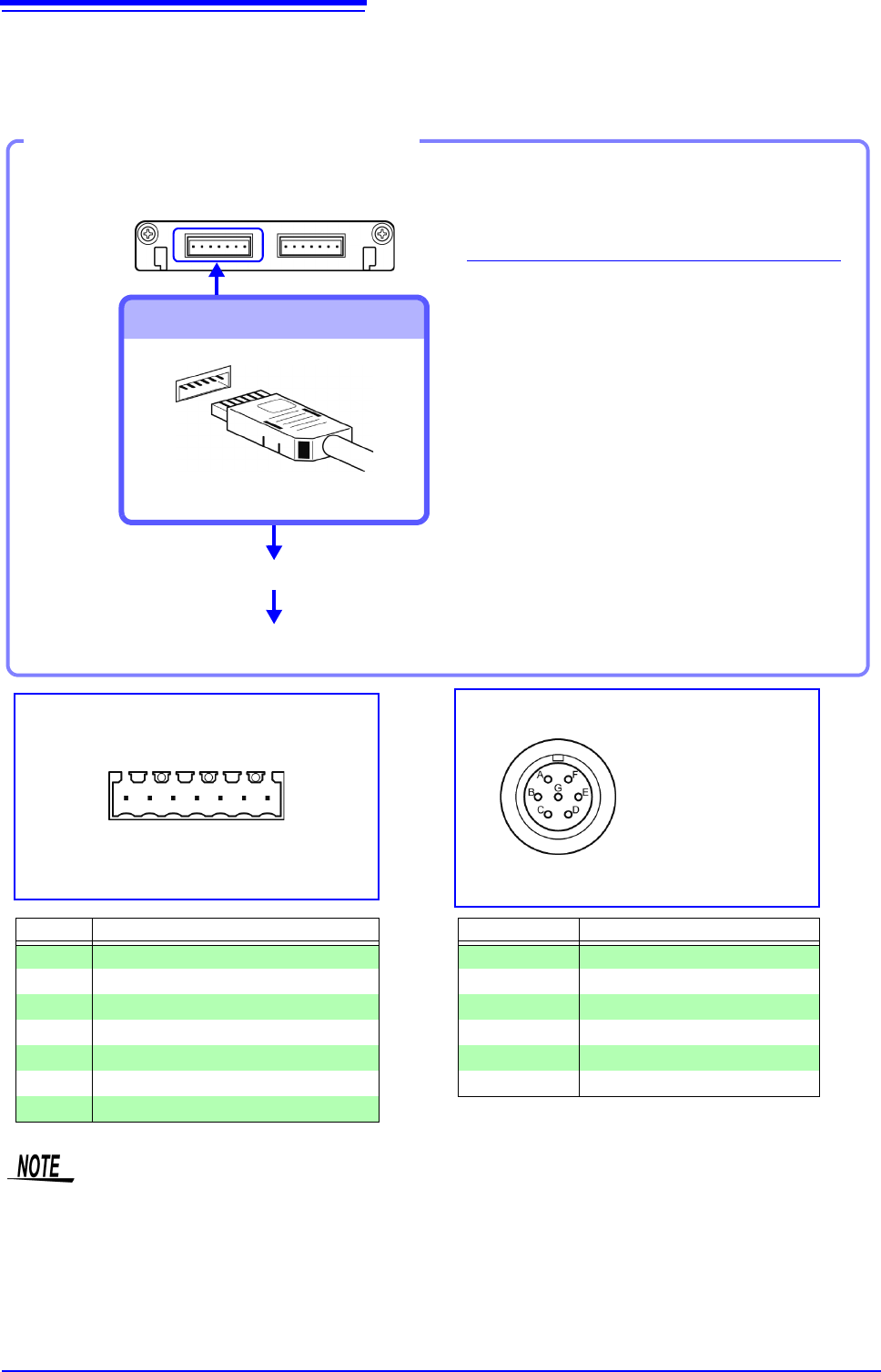
Connecting the 9769
1
Connect the 9769 to a terminal on the
module.
The orange section of the 9769 must
face up.
2
Connect the strain gauge transducer to
the conversion cable.
3
Attach to the measurement object.
Example: Connecting the 9769 Conversion Cable with the supplied conversion cable
Required item:
9769 Conversion Cable, strain gauge transducer
Connect to module's terminal
Connect to the strain gauge transducer
3
2
1
Applied voltage:
bridge voltage of 2 V
Connector Pinout of the 9769 on strain
gauge transducer side
The metal shell is connected to the GND
of Model 8969.
Connector Pinout of the 8969
(1 is on left when unit top side is facing up)
Pin No. Description
1 BRIDGE+
2 SENSE+
3 INPUT+
4 INPUT-
5 BRIDGE-
6 SENSE-
7 FLOATING COMMON
Pin Mark Description
A BRIDGE+
BINPUT-
C BRIDGE-
DINPUT+
E FLOATING COMMON
F, G N.C.
1234567
• Preforming measurement with a strain gauge requires a bridge box. Use a strain gauge and bridge box
both of which are commercially available.
• The bridge box may be susceptible to the effect of noise. For more information about how to ground the
bridge box, refer to its instruction manual or contact the manufacturer of the bridge box.
• Do not excessively bend the cable and the base between cable and connector, pull on them, nor twist
them. Doing so may cause the conversion cable to break.
8969 Strain Unit
Connection of Model L9769
• Pin F of the module end is connected with Pin A of the strain gauge transducer end.
• Pin G of the module end is connected with Pin C of the strain gauge transducer end.