MR8740、MR8741_user_manual_eng_20191016H.pdf - 第184页
7.9 Setting Details of Modules 172 Select Selections Description Off Calibration and synchronizati on are not performed. On Performs calibration and sync hronization. Synchroni za- tion Performs only synchronization betw…
7.9 Setting Details of Modules
171
6
Chapter 7 Utility Functions
7
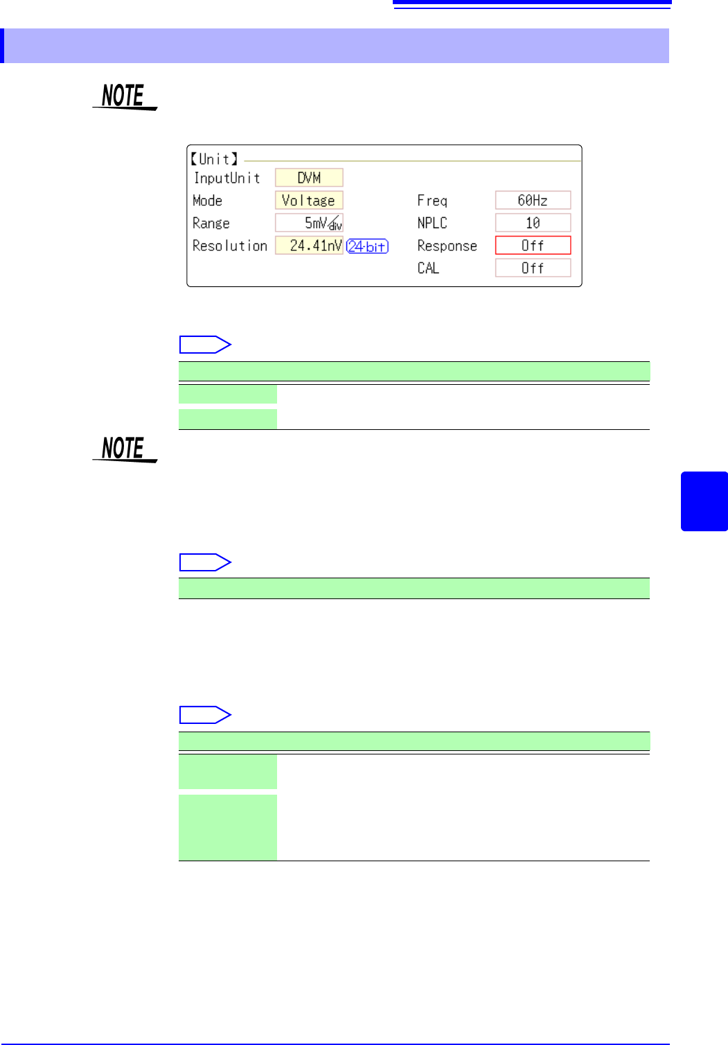
Frequency Set the power frequency.
Set 50 Hz or 60 Hz according to the power frequency for the region of use.
Select
NPLC PLC (Power Line Cycle) is the time equivalent to one cycle of the power fre-
quency.
Set the integration time based on one PLC.
Select
Example: When the power frequency is 50 Hz, and NPLC is set to 10, 20 ms x
10 = 200 ms.
The measurement data refresh rate becomes 200 ms.
Fast response Data can be refreshed at high speed.
Select
Calibration This setting is for performing calibration or synchronization between channels
automatically when measurement is started. Performing synchronization
between channels enables matching the timing for the start of integration.
7.9.8 Setting Model MR8990 Digital Voltmeter Unit
• When the MR8990 Digital Voltmeter Unit is installed on unit 1 (unit 1 or unit 2
in the case of MR8741), the standard logic can no longer be used.
• The resolution of the data measured by the recorder function is 16bit.
Selections Description
50Hz
Cycle 20 ms (default setting)
60Hz
Cycle 16.67 ms
If the power frequency setting is not configured correctly, measurement values
will be unstable.
0.1 to 0.9, 1 (default setting) to 10, 20, 30, 40, 50, 60, 70, 80, 90, 100
Selections Description
Off
Refreshes data at the integration time set for NPLC. (default set-
ting)
On
Calculates the moving average and refreshes the data at high
speed.
Refreshes the data at 0.1 PLC when NPLC is up to 9.
Refreshes the data at 1 PLC when NPLC is 10 or above.

7.9 Setting Details of Modules
172
Select
Selections Description
Off
Calibration and synchronization are not performed.
On
Performs calibration and synchronization.
Synchroniza-
tion
Performs only synchronization between channels.
• The calibration time is approximately 150 ms. That period becomes a waiting
time in which measurement is not performed.
• If synchronization between channels is performed, a signal to stop integration
is sent to each unit when measurement is started and the wait process is per-
formed until the first integration finishes. The wait time required for this process
is (10 ms + integration time
*
).
*The integration time varies depending on the NPLC setting.
If synchronization is not performed, the above wait time will also be required
for measurement performed immediately after the settings of the Digital Volt-
meter Unit are changed. However, there will be no wait time when measure-
ment is performed with the same settings.
• When this is set to OFF (default setting), perform calibration manually.
See:"2.7 Performing Calibration (When Mounting MR8990)" (p.59)
7.9 Setting Details of Modules
173
6
Chapter 7 Utility Functions
7
See: "Opening the [Each Ch] sheet, Making a Channel Selection" (p.161)
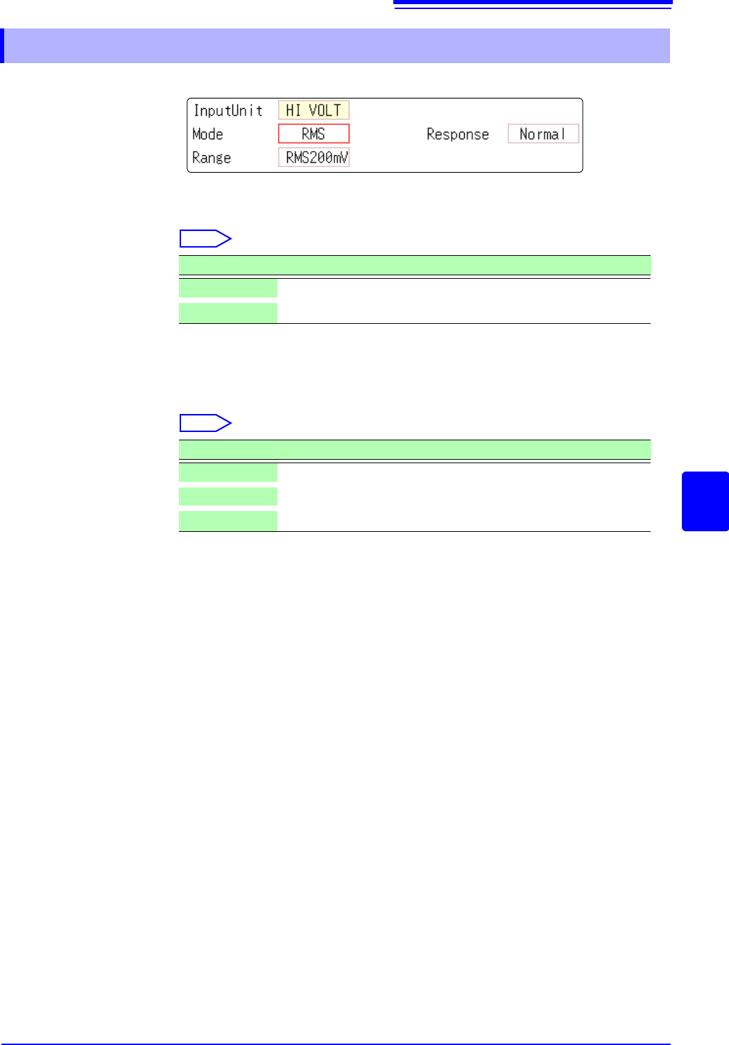
Mode Switches between voltage measurement and RMS measurement.
Select
Response The response time for RMS measurement can be set to three speeds: Fast, Nor-
mal and Slow.
The response time can be set to [Slow] to stabilize the measured value when
the frequency is low or when severe fluctuations are present.
Select
7.9.9 Setting Model Model U8974 High Voltage Unit
Selections Description
DC
Voltage measurement (Default setting)
RMS
RMS measurement
Selections Description
Fast
Response time is set to 150 ms.
Normal
Response time is set to 500 ms. (Default setting)
Slow
Response time is set to 2.5 s.