MR8740、MR8741_user_manual_eng_20191016H.pdf - 第192页
7.9 Setting Details of Modules 180 Output Turns waveform output On /Off. Select Contr ol Sets the waveform output. Select Metho d Selects the control method for waveform output. Select For details, see the instruction ma…
7.9 Setting Details of Modules
179
6
Chapter 7 Utility Functions
7
Channels installed with Model MR8791 cannot be measured.
See: "Opening the [Each Ch] sheet, Making a Channel Selection" (p.161)
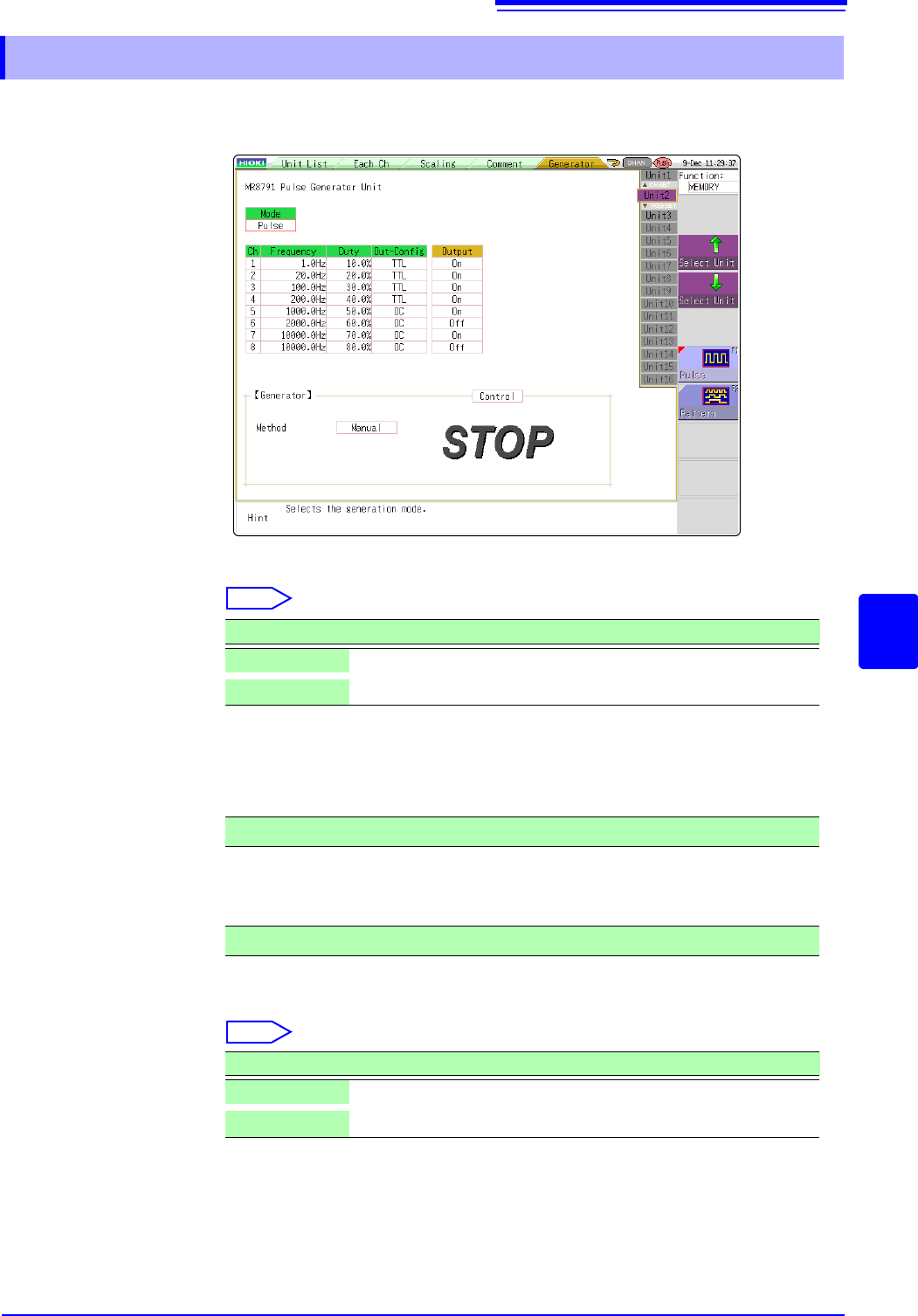
Mode Select the type of output.
Select
Refer to the instruction manual of Models U8793, MR8790, and MR8791 regard-
ing the detailed settings for pattern output.
Frequency Sets the frequency for pulse output.
Duty Sets the pulse duty.
Out-Config Sets the output status.
Select
7.9.12 Setting Model MR 8971 Pulse Generator Unit
Selections Description
Pulse
Pulse output (Default settings)
Pattern
Pattern output
0 Hz to 20000 Hz
0% to 100%
Selections Description
TTL
TTL output
OC
Open collector output

7.9 Setting Details of Modules
180
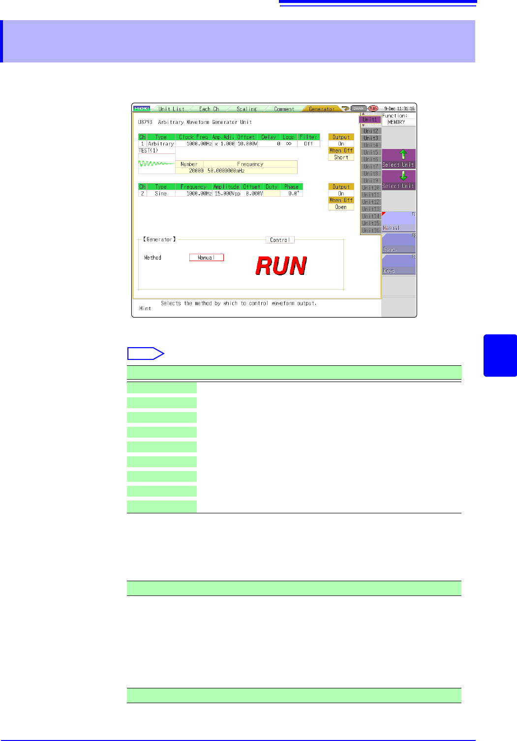
Output Turns waveform output On/Off.
Select
Control Sets the waveform output.
Select
Method Selects the control method for waveform output.
Select
For details, see the instruction manual of Models U8793, MR8790, and MR8791.
Selections Description
On
Outputs waveform.
Off
Does not output the waveform.
Selections Description
RUN
Starts output.
PAUSE
Pauses output. While output is paused, the output at the time
[PAUSE] was pressed will be output.
STOP
Stops output.
Selections Description
Manual
Restricts control of signal output to Signal Generation screen.
Sync.
Augments manual control with signal output in synchronization with
the start and end of measurement.
START key: Starts output when measurement starts.
STOP key: Stops output when measurement stops.
Sync.
Augments manual control by allowing signal output to be manipu-
lated using the instrument’s keys.
START key: Starts output.
STOP key: Stops output.
Manual Trigger key: Pauses output.
7.9 Setting Details of Modules
181
6
Chapter 7 Utility Functions
7
Channels installed with U8793 cannot be measured.
See: "Opening the [Each Ch] sheet, Making a Channel Selection" (p.161)
Type Selects the waveform type.
Select
Refer the instruction manuals of Model U8793, MR8790, and MR8791 for the
settings at the time of program selection.
Frequency Sets the frequency of output signal.
Amplitude Sets the amplitude of output signal.
The output voltage with guaranteed accuracy is the sum of the amplitude and the
offset, between -10 V and +10 V. If the sum of the amplitude and the offset is set
outside the guaranteed accuracy range, parts of the waveform will be clamped to
the upper limit, approximately +16 V and the lower limit, approximately -11 V.
7.9.13 Setting Model U8793 Arbitrary Waveform Gener-
ator Unit
Selections Description
DC DC output (Default setting)
Sine Sine wave output
Square Rectangular wave output
Pulse Pulse wave output
Triangle Triangular wave output
Ramp-up Ramp-up wave output
Ramp-down Ramp-up wave output
Arbitrary Outputs the created waveform
Program Outputs the waveform set in the program
0 Hz to 100000 Hz
0.000 V p-p to 20.000 V p-p