MR8740、MR8741_user_manual_eng_20191016H.pdf - 第227页
9.2 Settings for Numerical Value Calculat ion 215 Chapter 9 Numerical Calculat ion Functions 8 9 (2) Select the channel for calc ulations. Move the flashing cursor to the item for the calculation tar- get, and select the…
9.2 Settings for Numerical Value Calculation
214
9.2 Settings for Numerical Value Calculation
1
2
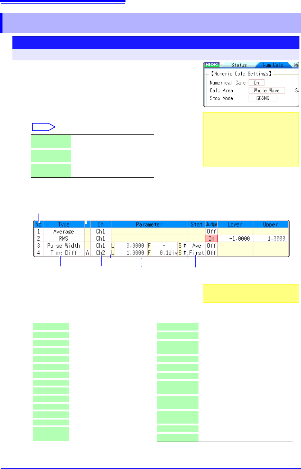
Procedure
To open the screen: Right-click and select [STATUS] [Num Calc] sheet
1
Enable the Numerical Calculation function.
Move the flashing cursor to the [Numerical Calc] item.
Select [On].
2
Specify the Numerical Calculation range.
Move the flashing cursor to the [Calc Area] item.
Select
See: "6.2 Specifying a Waveform Range (A/B Cursor)" (p.124)
3
Perform calculation settings.
(1)
Select the calculation type.
Move the flashing cursor to the number of the calculation type
for which to make settings, and select the calculation type.
(When you select [List] a list of calculation types appears.)
WholeWave Applies calculations to the whole
waveform. (default setting)
A-B Wave Applies calculations to the data be-
tween A/B cursors.
AfterTrigger Applies calculations to the waveform
after a trigger.
.Calculation No.
Calculation
Type
(1) (2) (3)
Parameters*
*: Setting choices depend
on the calculation type.
Channel for
Calculation
(4)
Statistical
calculation
(5)
Phenomenon
*2: Setting can also be made for logic channels
X-Y Area*
1
Area of X-Y composite waveform
Time to Lev*
2
Time from trigger to specified level
Lev-time Measurement value at a specified time
point after triggering
Pulse Width*
2
Pulse width of waveform data
Duty Ratio*
2
Duty of waveform data
Pulses*
2
Pulse count of waveform data
Calculation Four arithmetic operations on numerical
calculation results
Time Diff*
2
Time difference between phenomenon A
and B.
Phase Diff*
2
Time difference between phenomenon A
and B displayed as a phase contrast.
High Level*
1
High level value for waveform data
Low Level*
1
Low level value for waveform data
*1: Calculation performed with MR8990 Digital Volt-
meter Unit is invalid. The indication of the calcu-
lation result becomes "******".
Off No calculation. (default setting)
Average Average value of waveform data
Rms*
1
RMS value of waveform data
Peak-Peak Peak-to-peak value of waveform data
Maximum Maximum value of waveform data
Max-Time Time from trigger to maximum value
Minimum Minimum value of waveform data
Min-Time Time from trigger to minimum value
Period*
2
Period of signal waveform
Frequency*
2
Frequency of signal waveform
RiseTime*
1
Rise time of waveform data
FallTime*
1
Fall time of waveform data
Std Dev*
1
Standard deviation of waveform data
Area*
1
Area enclosed by zero position and
signal waveform
When selecting [A-B Wave], specify the
calculation range using the A/B cursors on
the Waveform screen.
If no measurement data has been ac-
quired by the instrument, first measure
once so that the range can be specified for
calculations to be applied to subsequent
measurements.
Also select [Judge] if you require judg-
ment of calculation results.(p.218)

9.2 Settings for Numerical Value Calculation
215
Chapter 9 Numerical Calculation Functions
8
9
(2)
Select the channel for calculations.
Move the flashing cursor to the item for the calculation tar-
get, and select the channel.
(A logic channel can also be selected for Time to Level, Pulse Width, Duty
Cycle, and Pulse Count.)
(3)
Set parameters.
Settings may not be necessary for some calculation types
When calculating time differences and phase contrast,
makes settings for A and B channels.
Move the flashing cursor to the parameter items, and make
appropriate parameter settings.
See: "Parameter table" (p.216)
See: "7.1.3 Alphanumeric Input" (p.141)
(4)
Set the statistical calculation.
Move the flashing cursor to the [Stat] column.
Select
(5)
When time difference calculation or phase contrast cal-
culation has been selected, set Ch (channel) and param-
eters for A and B.
4
Execute the calculations. (when judging calculations
(p.218))
Applying Calculations to Existing Data
Select [Exec].
When calculating automatically after measurement
Click [START] to start measurement.
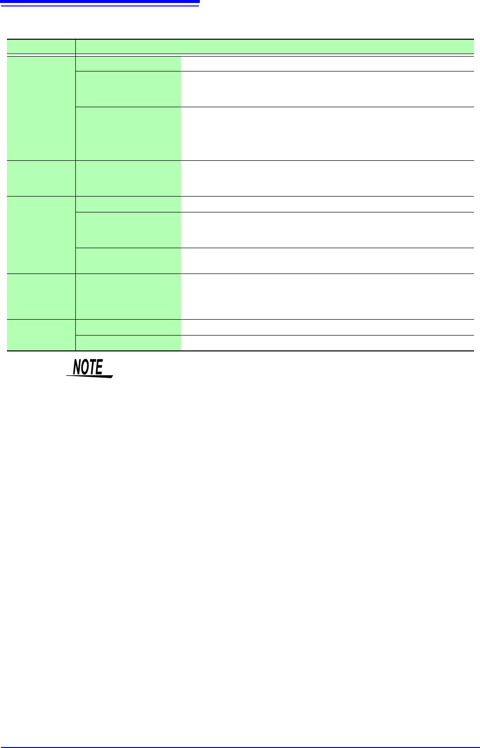
First Calculate at the first condition of the measurement data.
Average Acquire the average value of the calculation result in the
measurement data.
Max Acquire the maximum value from the calculation result in
the measurement data.
Min Acquire the minimum value from the calculation result in
the measurement data.
When saving calculation results during
measurement
Settings must be made before the mea-
surement.
See: "9.4 Saving Numerical Calculation
Results" (p.221)
When saving existing data
Click [SAVE].
See: "4.2.3 Saving Data Selectively
(SAVE)" (p.93)
To copy a calculation setting to another calculation number
Use the [Num Calc] sheet.
See: "7.8 Copying settings to other channels (calculation No.) (Copy function)" (p.160)
9.2 Settings for Numerical Value Calculation
216
Parameter table________________________________________________
Calculation Type Parameter Parameter description
Period
Frequency
Pulse Width
Pulses
Duty Ratio*
Time Diff
Phase Diff
*: Level and
Filter only
L (Level) Calculation is based on the interval (time) when this level is crossed.
F (Filter)
Only when the measurement signal has crossed the level and has not crossed the
level again within the specified filter width, it is taken as a valid event. This is useful
to exclude level crossing events due to noise.
S (Slope(, ))
Calculation is based on the interval (time) when the level is crossed.
Depending on this setting, either crossing on the upward slope () or downward
slope () is used for calculation.
Risetime
Falltime
P (%)
Determines which section of the waveform between the upper and lower limits is
used for risetime (or falltime) calculation. The range is narrowed from the upper and
lower limit values by the percentage set here.
Time to Lev
L (Level) Calculates the time specified level is crossed.
F (Filter)
Only when the measurement signal has crossed the level and has not crossed the
level again within the specified filter width, it is taken as a valid event. This is useful
to exclude level crossing events due to noise.
S (Slope(, ))
Determines whether the time is calculated until the signal crosses the specified lev-
el on the upward slope or on the downward slope.
Lev-Time
Time or Measure (Calcula-
tion results)
Specifies the time for calculating the measurement value, using the trigger position
as zero.
To use the numerical calculation result, specify the numerical calculation number.
The range specified by A/B cursors is not available.
Calculation
Numerical Calculation No. Sets the numerical calculation number.
+, - , ×, ÷ Sets the operators for the four arithmetic operations.
• Depending on the signal waveform, calculation values for the Period, Fre-
quency, Risetime, and Falltime parameters may not be displayed.
• When Scaling is enabled, the waveform data are scaled before numerical cal-
culation. The units for parameter values are derived from the units set for the
Scaling function.
See: About Scaling: "7.4 Converting Input Values (Scaling Function)" (p.148)