MR8740、MR8741_user_manual_eng_20191016H.pdf - 第56页
2.2 Connecting Cords 44 Att ach to the meas urement object Connecting the 9769 1 Connect the 9769 to a termina l on the module. The orange section of the 9769 must face up. 2 Connect the strain gauge transducer to the co…
2.2 Connecting Cords
43
2
Chapter 2 Measurement Preparations
Applicable Modules
• Model U8969 Strain Unit
• Model 8969 Strain Unit
The following device can be connected to the module.
• Strain Gauge Transducer (Not available from Hioki)
• Connect L9769 or 9769 Conversion Cable to the strain gauge
Measuring vibration or displacement with a strain gauge transducer
Connect a strain gauge transducer to a connector on Model U8969 Strain Unit via Model L9769 Conversion Cable; Mod-
el 8969 Strain Unit via Model 9769 Conversion Cable.
The instrument describes Model U8969 as “8969”.
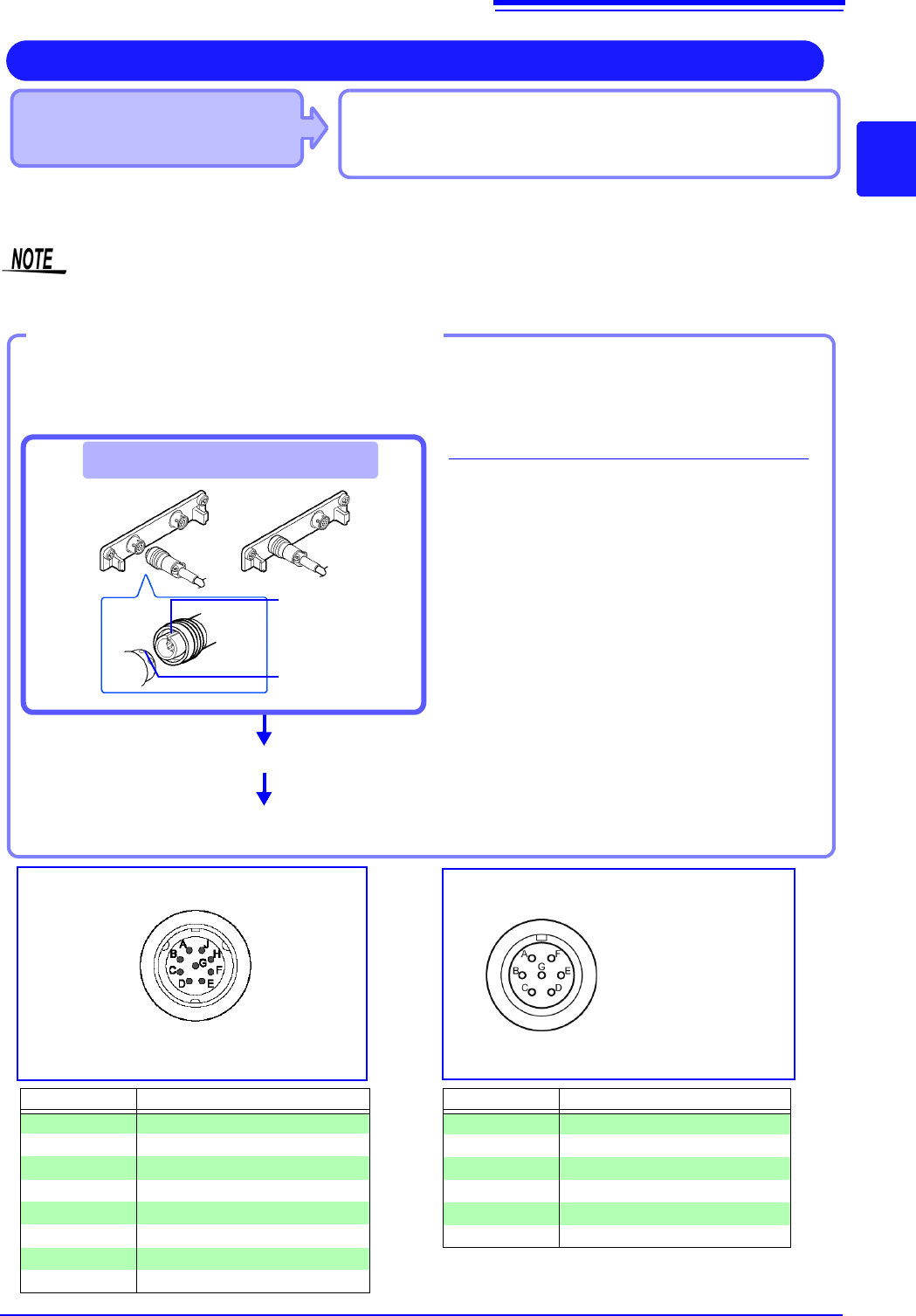
Connect the strain gauge transducer to a
measurement object.
Connecting the L9769
1
Insert Model L9769 into a connector of
Model U8969 with the slot of the plug
aligned with the outward indentation of
the connector.
2
Insert the plug into the connector until
they are locked together.
3
Connect Model L9769 to the strain
gauge transducer.
4
Connect the strain gauge transducer to
a measurement object.
Example: Connecting the strain gauge transducer to Model U8969 Strain Unit via Model L9769 Con-
version Cable
Required items:
Model L9769 Conversion Cable, strain gauge trans-
ducer
Connect to module's terminal
Connect Model L9769 to the strain gauge
transducer.
Applied voltage: bridge
voltage of 2 V
Connector Pinout of the L9769 Conversion
Cable on strain gauge transducer side
4
3
1
The metal shell is connected to the GND
of the instrument.
Connector Pinout of the U8969
Pin Mark Description
A BRIDGE+
B INPUT+
C BRIDGE-
D INPUT+
E FLOATING COMMON
F SENSE+
G SENSE-
H, J N.C.
Pin Mark Description
A BRIDGE+, SENSE+
BINPUT-
C BRIDGE-, SENSE-
DINPUT+
E FLOATING COMMON
F, G N.C.
The metal shell is connected to the GND
of the instrument.
How to disconnect Model L9769
Pull the sleeve of the plug gently, releasing the
plug, and disconnect the cable.
2
Plug’s slot
Connector’s inden-
tation
2.2 Connecting Cords
44
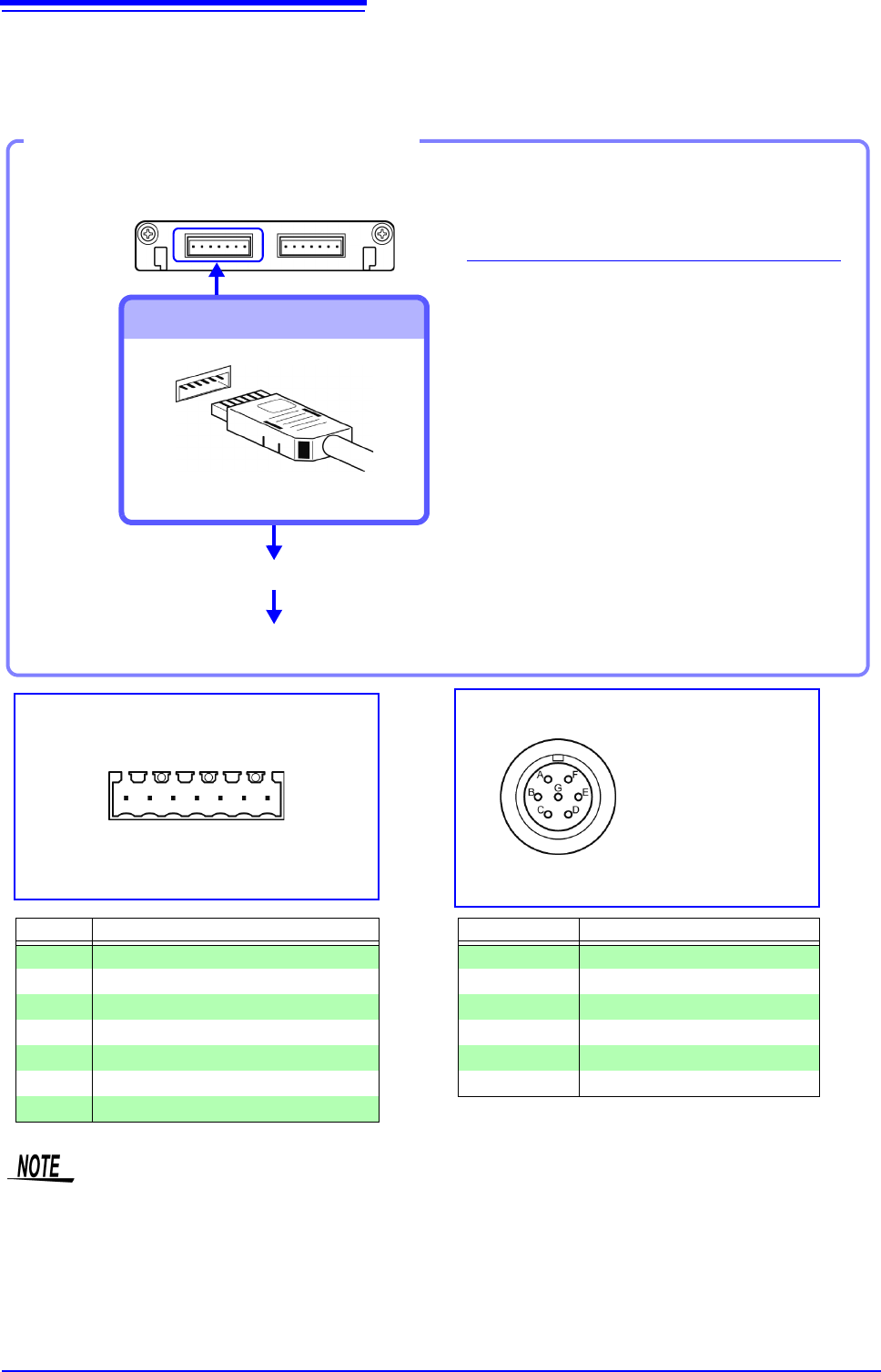
Attach to the measurement object
Connecting the 9769
1
Connect the 9769 to a terminal on the
module.
The orange section of the 9769 must
face up.
2
Connect the strain gauge transducer to
the conversion cable.
3
Attach to the measurement object.
Example: Connecting the 9769 Conversion Cable with the supplied conversion cable
Required item:
9769 Conversion Cable, strain gauge transducer
Connect to module's terminal
Connect to the strain gauge transducer
3
2
1
Applied voltage:
bridge voltage of 2 V
Connector Pinout of the 9769 on strain
gauge transducer side
The metal shell is connected to the GND
of Model 8969.
Connector Pinout of the 8969
(1 is on left when unit top side is facing up)
Pin No. Description
1 BRIDGE+
2 SENSE+
3 INPUT+
4 INPUT-
5 BRIDGE-
6 SENSE-
7 FLOATING COMMON
Pin Mark Description
A BRIDGE+
BINPUT-
C BRIDGE-
DINPUT+
E FLOATING COMMON
F, G N.C.
1234567
• Preforming measurement with a strain gauge requires a bridge box. Use a strain gauge and bridge box
both of which are commercially available.
• The bridge box may be susceptible to the effect of noise. For more information about how to ground the
bridge box, refer to its instruction manual or contact the manufacturer of the bridge box.
• Do not excessively bend the cable and the base between cable and connector, pull on them, nor twist
them. Doing so may cause the conversion cable to break.
8969 Strain Unit
Connection of Model L9769
• Pin F of the module end is connected with Pin A of the strain gauge transducer end.
• Pin G of the module end is connected with Pin C of the strain gauge transducer end.
2.2 Connecting Cords
45
2
Chapter 2 Measurement Preparations
When measuring current with a 9018-50 Clamp On Probe
You can use a voltage measurement unit such as the 8966 Analog Unit to make measurements. For more
information about how to configure the instrument for use in this type of application, see the example settings
in "7.4.1 Scaling Setting Examples" (p.150).
Applicable Modules
• Model 8971 Current Unit
Use to connect: Clamps
• Model 9272-10
Clamp On Sensor
• Model 9709, CT6862, CT6863,
CT6865
AC/DC Current Sensor
• Model CT6841, CT6843,
CT6844, CT6845
AC/DC Current Probe
Example:
9272-10+9318
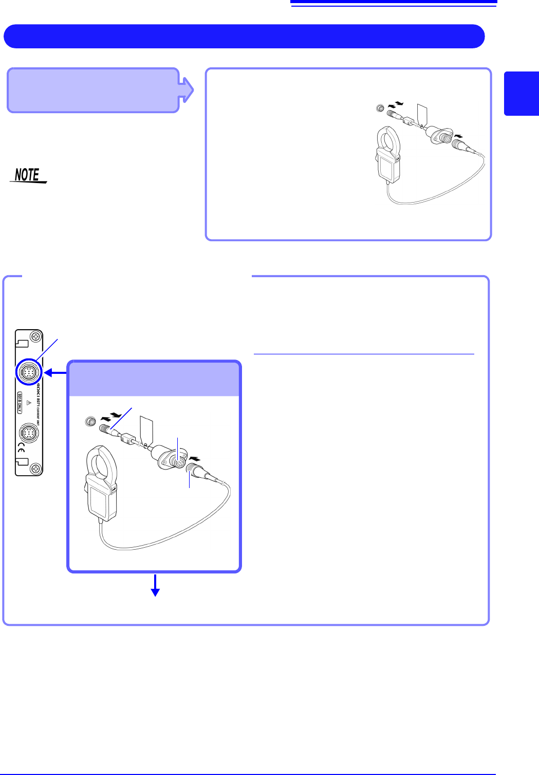
Measuring Current
Coneect Model 9318 Conversion Cable to
the module jack.
• 8971 Current Unit cannot be used with
MR8741.
• With MR8740, up to four 8971 Current
Units can be used.
1
Align the grooves of the unit sensor
connector and the conversion cable
plug. Insert the plug until it locks.
2
Align the grooves of the conversion
cable connector and the plug of the
clamp-on sensor to be used. Insert
the plug until it locks.
3
Connect the clamp sensor to the item
to be measured.
To disconnect the conversion cable:
Slide the plug to release the lock and
then unplug the cable.
Example: When connecting the 9272-10 Clamp On Sensor
Required item:
9318 Conversion Cable、9272-10 Clamp On Sensor
Sensor connector
Connect to module's terminal
Attach to the measurement object
Connecting the 9318 Conversion
Cable and clamp
Conversion cable
connector
2
1
Conversion cable plug
Model 9272-10
Clamp-on sen-
sor plug
3