MR8740、MR8741_user_manual_eng_20191016H.pdf - 第161页
7.4 Converting Input Values (Scaling Function) 149 6 Chapter 7 Utility Functions 7 2 3 4 1 2 4 3 4 Procedure To open the screen: Right-click and select [CHAN] [Each Ch] sheet 1 Enable the Sca ling function. Select Move…
7.4 Converting Input Values (Scaling Function)
148
About the Scaling
Function
Use the scaling function to convert the measured voltage units output from a sensor
to the physical units of the parameter being measurement.
Hereafter, "scaling" refers to the process of numerical value conversion using
the Scaling function.
Gauge scales, scale values (upper and lower limits of the vertical axis (voltage
axis)) and A/B cursor measurement values can be displayed in scaled units.
Scaling is available for each channel.
Scaling Setting Example
See: When using a clamp sensor (p.150) (Example: Converting [ V ] [ A ])
When using the Strain Unit (p.151) (Example: Converting [
] [ G ])
Scaling Methods Two scaling methods are available:
• Conversion Ratio Setting
• Two-Point Setting
7.4 Converting Input Values (Scaling Function)
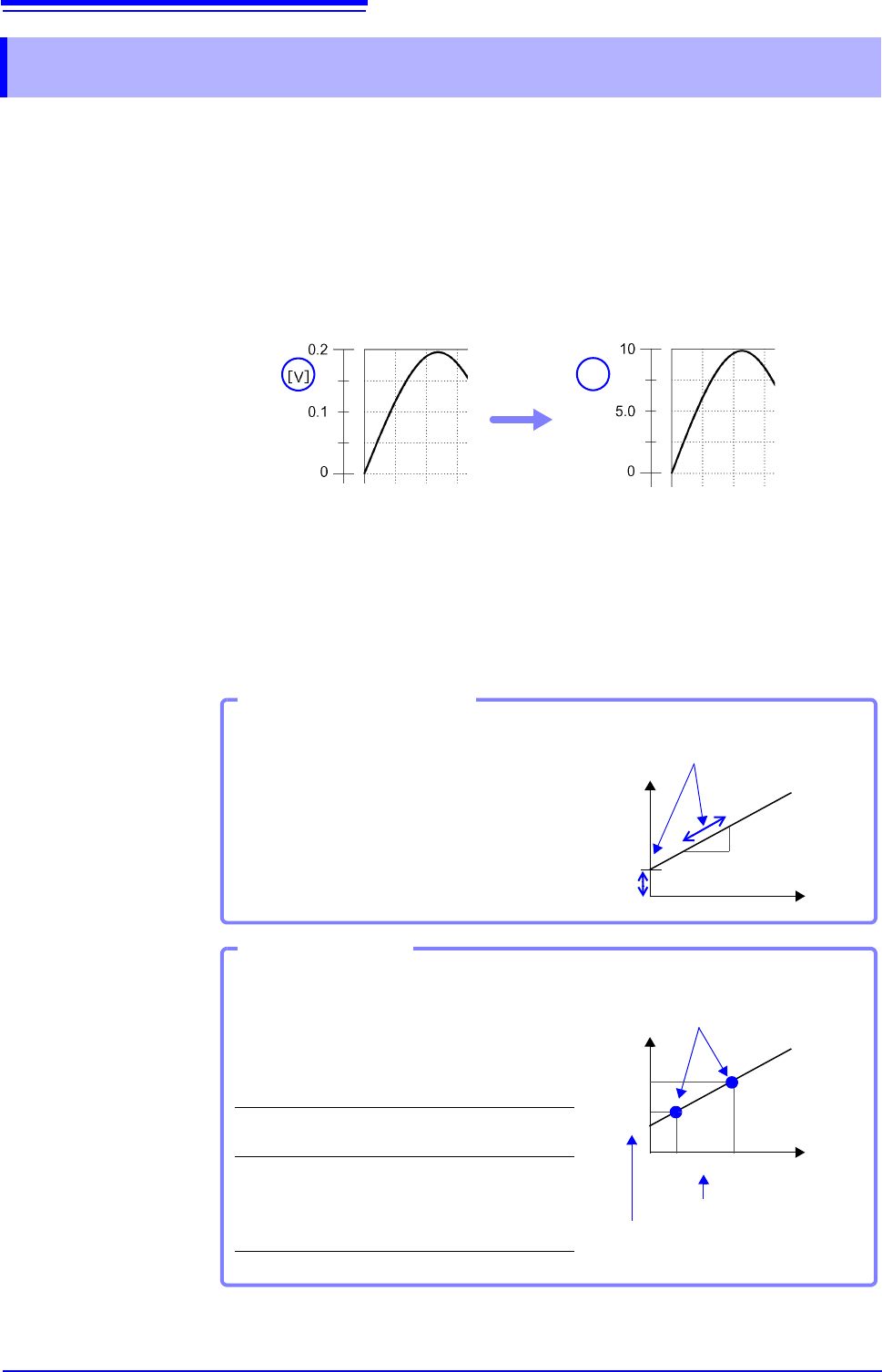
[A]
Before Scaling After Scaling
Set the physical value per volt (conversion ratio:
eu/V) of the input signal, an offset value and mea-
surement unit name (eu: engineering units) for
conversion, so measurement values acquired as
voltage are converted to the specified units.
Example:
Conversion ratio: A value per volt, Offset value:
B, Unit name: A
Conversion Ratio Setting
[A]
[V]
Convert from slope (conversion ra-
tio) and offset value
B
(:Example: Converting [V] [A])
Set the voltage values of two points of the input
signal, the converted unit value of these two
points and the name of the converted measure-
ment units, so measurement values acquired as
voltage are converted to the specified units.
Example:
Unit name: A
Voltage value at
2 points
Voltage of units to
convert
V
H
: Higher poten-
tial point
A
H
: Value for higher
potential point
V
L
: Lower poten-
tial point
A
L
: Value for lower
potential point
Two-Point Setting
A
H
A
L
V
L
V
H
[A]
[V]
Conversion ratio and offset value are
calculated from the two points and
converted
Actual measurement values
Converted unit values
7.4 Converting Input Values (Scaling Function)
149
6
Chapter 7 Utility Functions
7
2
3
4
1
2
4
3
4
Procedure
To open the screen: Right-click and select [CHAN] [Each Ch] sheet
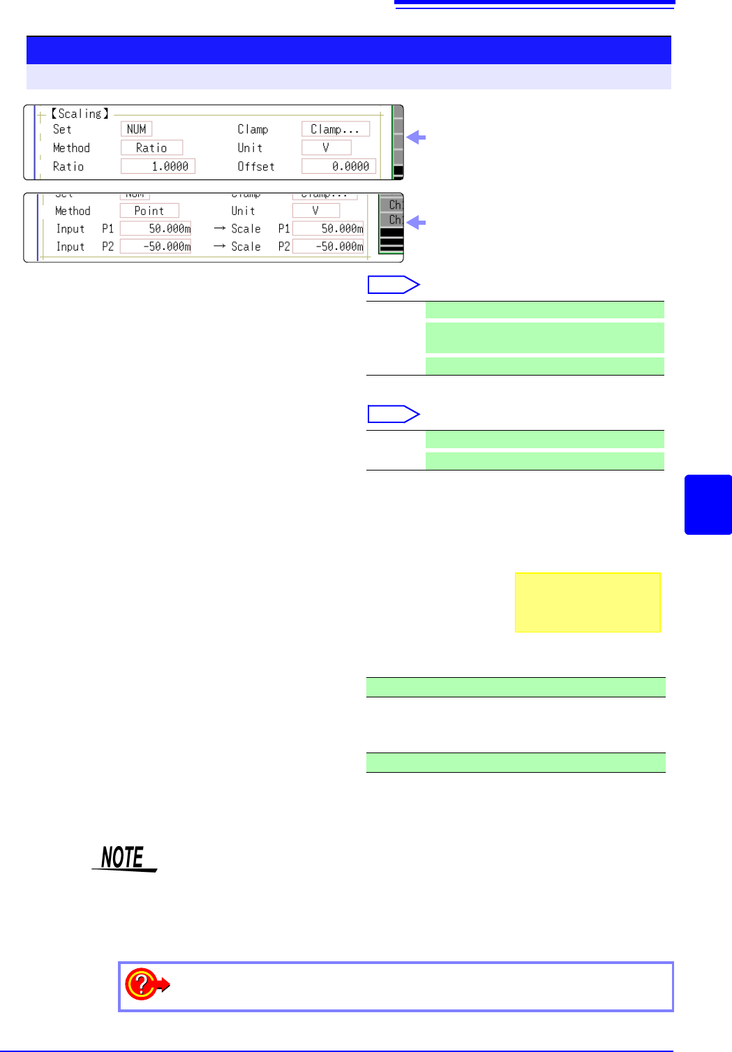
1
Enable the Scaling function.
Select
Move the flashing cursor to the [Disp] item.
2
Select the scaling conversion method.
Select
Move the flashing cursor to the [Method] item.
3
Specify the physical units.
Move the flashing cursor to the [Unit], and enter
the physical unit name. (Up to 7 characters)
See: "Entering Text" (p.141)
4
Enter the numerical values for conversion.
When you have selected [Ratio] (set conver-
sion ratio and offset)
Move the flashing cursor to the [Ratio] and [Off-
set] items.
Enter numerical values in each field.
When you have selected [2-Point] (set input val-
ues for two points and the values after conver-
sion)
Move the flashing cursor to the [Input P1], [Scale
P1], [Input P2], and [Scale P2].
Enter numerical values in each field.
Off No scaling.
NUM
Displayed as a decimal and includes a unit (m,
k, etc.).
SCI
Displayed as an exponent (the power of ten)
Ratio Specify by conversion ratio.
Point
Specify by two points.
-9.9999E+9 to 9.9999E+9
-9.9999E+9 to 9.9999E+9
Input example:
Decimal1.2345 mV
Exponent1.2345E-03V
Display selecting [Ratio] for [Method] item
Display selecting [Point] for [Method] item
• When saving text or results of numerical calculation, some characters and
symbols used for display on the instrument will be converted as follows.
(MR8740/MR8741 display saved string)
•
2
^2,
3
^3, ~u, ~o, ~e, °~c ,
±~+, (display only)uE, °C (display only)C
To enter the current input value as is for P1 or P2
Select [Monitor Val].
7.4 Converting Input Values (Scaling Function)
150
The 9018-50 Clamp On Probe provides 0.2 V output when measuring 10 A. So
Scaling should be set to display 10 A with 0.2 V input (and 0 A with 0 V input).
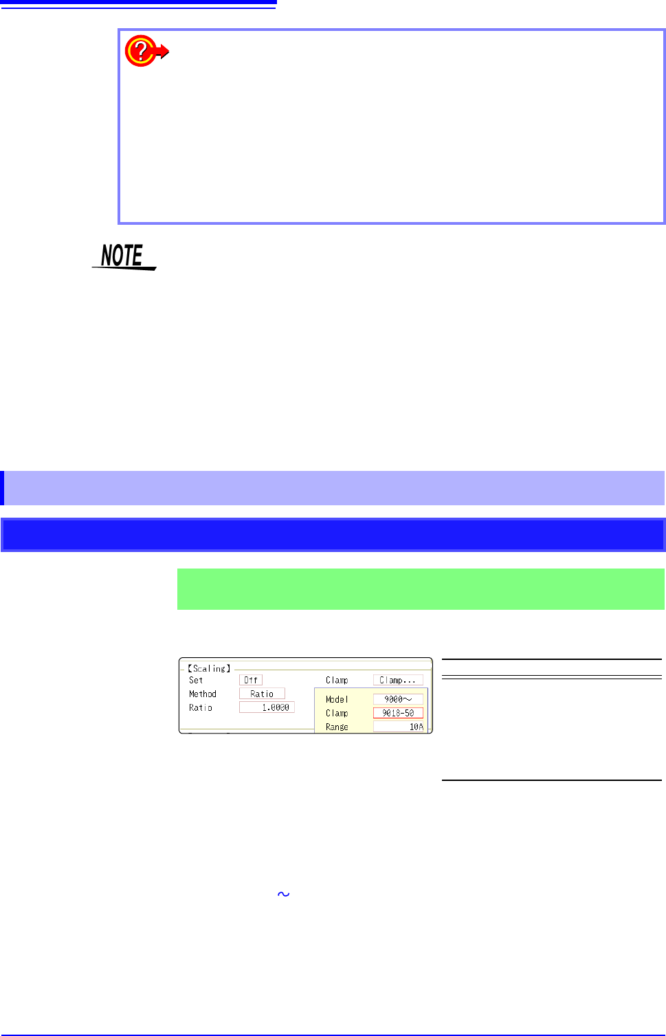
Selecting a Clamp Type ___________________________________________
1. Move the flashing cursor to the [Clamp] item, and select [Select].
The flashing cursor moves to the [Model] item.
2. Select [9000 ].
The flashing cursor moves to the [Clamp].
3. Select [9018-50] from the clamp list and select [Confirm].
Units, scaling method, and ratio are set automatically.
4. Select the same range of the clamp when using the range selection type.
Select [10A] here.
To reset Scaling settings:
Move the flashing cursor to the [Setting], and select [Reset].
To copy the scaling setting to another channel
The Channel screen - [Scaling] sheet can be used to copy a setting.
See: "7.8 Copying settings to other channels (calculation No.) (Copy function)" (p.160)
Using the Scaling and Variable functions (p.155) in combination:
The full span of output from a sensor can be displayed. (p.157)
At factory shipping, automatic correction of the variable function (p.311) is set to
[On].
At this time, the Variable setting is altered so that it is linked to (dependent upon)
the vertical axis (voltage axis) range and scaling settings. If you want the Vari-
able function setting to take priority, use either of the following procedures:
• Set Scaling first, and then set the Variable function
• Set a Variable value before Scaling, and then set Scaling.
When automatic correction of the Variable function (Variable Auto Adjustment) is
disabled ([Off]), the Scaling and Variable settings are unlinked (independent of
one another).
7.4.1 Scaling Setting Examples
Using a Clamp-On Probe
Example 1
Measure with the 10 A range of the Model 9018-50 Clamp On Probe and
display the measured data in units of [A] (Amperes)
Setting Items Setting Choice
Disp NUM or SCI
Clamp 9018-50
Unit
*
A
Method
*
Ratio
Ratio
*
50.000
*: Set automatically when clamp is selected.