MR8740、MR8741_user_manual_eng_20191016H.pdf - 第344页
15.5 Controlling the Instrumen t with Command Communications (LAN) 332 You can control the instrument remotely o ver the communications interface (LAN). • For details, see the communications related documentation on the …
15.4 Wave Viewer (Wv)
331
12
Chapter 15 Connection to a Computer
14
15
The viewer has a CSV conversion function. Converted files may be read by a spreadsheet program.
This section explains how to install and uninstall and how to start and quit the
Wave Viewer.
System requirements
System requirements: PC running Windows 7, Windows 8, or Windows 10.
1. When you insert the Application Disk (CD-R) into the CD-ROM drive, the open-
ing page should appear automatically.
If it does not appear, open the "index.htm" file with your Web browser.
2. Select the language to display (click the English icon).
3. Click the [Wave viewer (Wv)] icon to view Wv specifications and revision his-
tory.
4. Click the [Install] icon at the top right of the page to open the [File Download]
dialog.
5. Click [Open] to display the confirmation dialog to proceed with installation. And
go on the procedure.
6. Click [Next] to open the installation destination selection window.
Click the [Browse] button to change the installation folder.
7. Click [Next] to start installation.
The program is now installed.
Before using the program, review the "READ ME" text file.
In the Windows
®
Start menu, select [Programs] - [HIOKI] - [Wv.] This starts the
Wave Viewer application.
Access the menus of the Wave Viewer application and select [File] - [Exit] to
shut down the program. Alternatively, you can click the Close button at the top
right of the screen.
1. Click the Windows
®
Start button, click [Control Panel], and then click [Uninstall
a program].
The list of the installed programs appears.
2. Select [HIOKI Wave Viewer (Wv)] and uninstall the application.
To upgrade to a newer version, uninstall the old version first and then install the
new version.
15.4 Wave Viewer (Wv)
Installation (Windows 7)
Startup
Shutdown
Uninstallation
15.5 Controlling the Instrument with Command Communications (LAN)
332
You can control the instrument remotely over the communications interface (LAN).
• For details, see the communications related documentation on the supplied application
disc.
• Before using command communications, the LAN settings and connection must have
been established properly.
See: LAN"15.1"(p.314)
15.5 Controlling the Instrument with Command
Communications (LAN)
In an environment where noise from inverters or similar devices is present,
errors may occur when controlling the instrument remotely. Take care to ensure
that the environment is not subject to excessive noise.
About Setting Items
Delimiter The Delimiter item specifies LF or CR+LF as the newline delimiter in command response messages. The
instrument understands all three settings: LF or CR+LF.
Header Use for control of communications commands.
The Header item specifies whether to prefix headers to command response messages.
For more information about commands, refer to the Communications operation manual on the supplied CD.
Command Port
(Port number)
The instrument uses the TCP/IP protocol for communications. TCP/IP allows communicating devices to es-
tablish multiple connections, which are distinguished by port numbers.
By default the instrument uses port numbers 8800 to 8809.
•8800 to 8801 reserved
•8802 (instrument is server): For communications command control
•8803 to 8809 reserved
Normally these ports do not need to be changed. You can change them if certain ports cannot be used for
security reasons, or if certain ports are not available on the communicating PC. Set only the most significant
three digits. The least significant digit (0 to 9) is used by the instrument, or reserved for use by the instru-
ment.
15.5 Controlling the Instrument with Command Communications (LAN)
333
12
Chapter 15 Connection to a Computer
14
15
Set items related to command communications.
15.5.1 Making Settings on the Instrument
1
2
3
1
Set the delimiter.
Select
Move the flashing cursor to the [Delimiter]
item.
2
Make header settings.
Select
Move the flashing cursor to the [Header]
item.
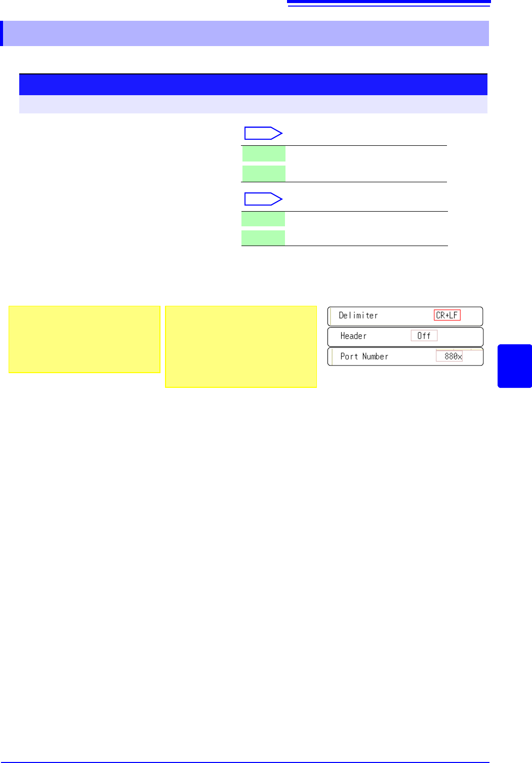
3
Set the communications command port.
Move the flashing cursor to the [Port Number] item, and enter the port number.
LF Send character code 0x0a.
CR+LF Send character codes 0x0d and 0x0a.
Off Do not add a header to response data.
On Add a header to response data.
Procedure
To open the screen: Right-click and select [SYSTEM] [Interface] sheet
About port numbers
Specify only the most significant 3 digits
of the 4-digit port number.
If you specify "880x", port number 8802 is
used.
"Command Port (Port number)"
(p.332)
About headers
The response to a :FUNCTION? query
command from the PC differs according
to the header setting.
On ................... :FUNCTION MEM
Off ................... MEM