MR8740、MR8741_user_manual_eng_20191016H.pdf - 第166页
7.4 Converting Input Values (Sca ling Function) 154 1. For scaling, set the [Method] to [Ratio] . 2. Point the flashing cursor to the conversion rate setting and select [dB Scal- ing] . 3. In the displaye d entry field a…

7.4 Converting Input Values (Scaling Function)
154
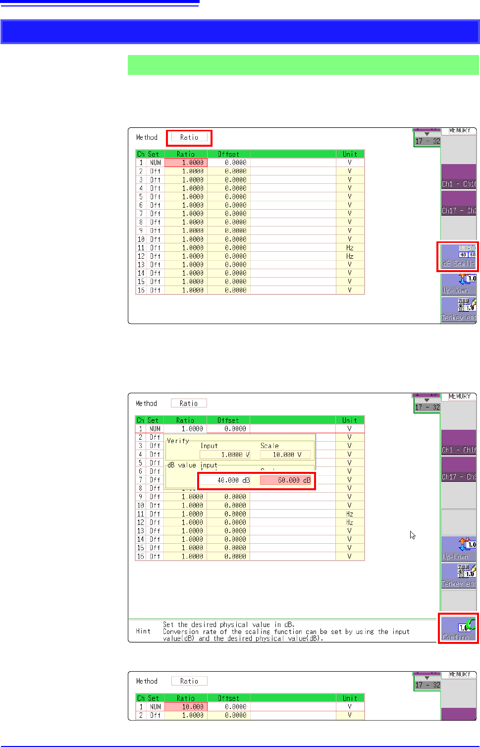
1. For scaling, set the [Method] to [Ratio].
2. Point the flashing cursor to the conversion rate setting and select [dB Scal-
ing].
3. In the displayed entry field and physical quantity field, enter 40 dB and 60 dB,
respectively.
After entering the values, select [Confirm].
See: "7.1.3 Alphanumeric Input" (p.141)
The conversion rate for the entered dB value is entered. (The offset becomes 0.)
Using the dB value
Example 5
Acquiring the conversion rate to convert 40 dB input to 60 dB
1
2
2
7.5 Variable Function (Setting the Waveform Display Freely)
155
6
Chapter 7 Utility Functions
7
The waveform height and display position can be arbitrarily set along the vertical axis (voltage axis).
The following two setting methods are available:
• Set the displayed amplitude per division (1div setting)
Set the amplitude to be displayed per vertical division and the zero position of
the waveform on the vertical axis (voltage axis).
• Set the Upper and Lower Limits (Upper-Lower setting)
The upper and lower limits on the vertical axis (voltage axis) can be set to dis-
play the waveform amplitude full-screen.
Settings for the Variable function can be made for each individual channel, using
the [Each Ch] sheet accessed from the Channel screen (p.156), or for all chan-
nels using the Display range window (p.157).
7.5 Variable Function (Setting the Waveform Dis-
play Freely)
Precautions for using the Variable Function
• Verify that the vertical axis (voltage axis) range is set properly for the input sig-
nal.
• The vertical axis (voltage axis) range is unaffected by changes to the upper
and lower limits made by the Variable setting.
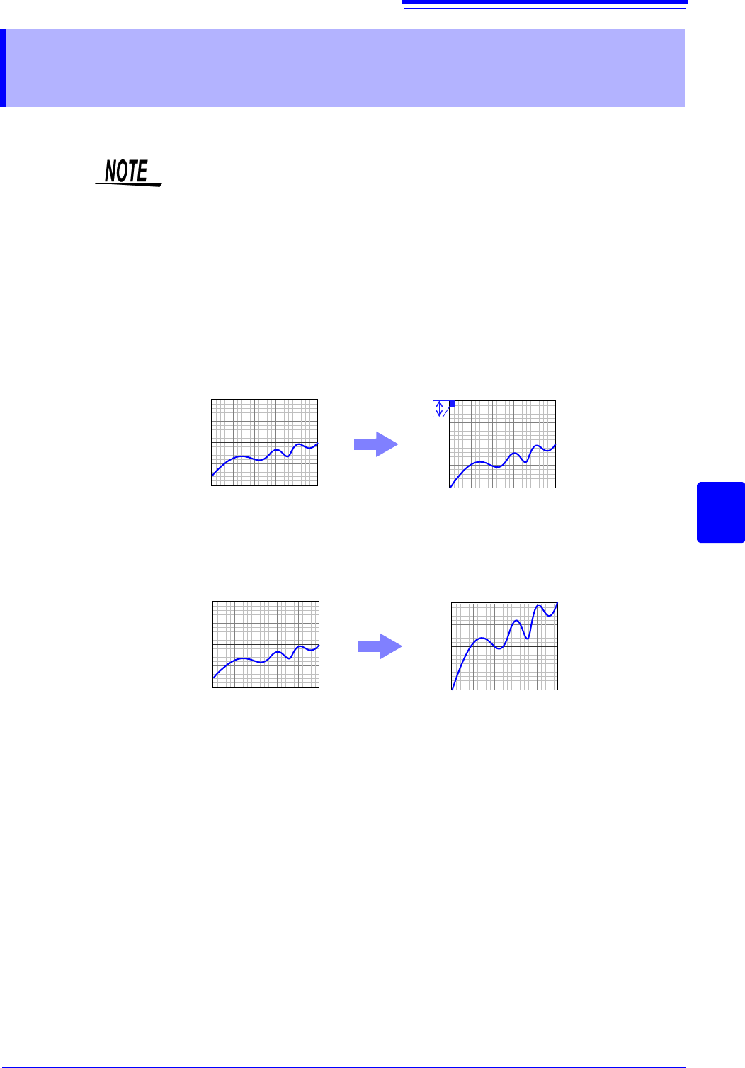
Normal Waveform
Variable Function (Per-Division setting)
0V
10V
0V
1V
Per Division: 1 V
Zero Position: 0%
Normal Waveform Variable Function (Set Upper/Lower Limits)
0V
10V
0V
10V
Upper Limit: 10 V
Lower Limit: 0 V