MR8740、MR8741_user_manual_eng_20191016H.pdf - 第77页
3.4 Setting Measurement Configuration 65 3 Chapter 3 Measuremen t Procedure Set measurement conditions as follows. By calling up the Waveform screen and then using the Settings window to make basic settings, you can imme…
3.3 Pre-Measurement Inspection
64
The following steps should be performed before measurement.
3.3 Pre-Measurement Inspection
Before using the instrument the first time, verify that it operates normally to ensure that the no
damage occurred during storage or shipping. If you find any damage, contact your dealer or Hioki
representative.
Do not use if damage is present,
as you could receive an electric
shock. Replace the damaged
items.
Metal Exposed
Is the insulation of the probe or connection
cable to be used damaged, or is bare metal
exposed?
When using probes and connection cables
When using a clamp
Is the clamp cracked or damaged?
Yes
1
No Metal Exposed
2
Go to
No
2
Go to
Peripheral Device Inspection
If damage is evident, request re-
pairs.
Yes
Is damage to the instrument or modules evi-
dent?
Instrument and Module Inspection
When turning power on
Do the fans rotate and the Hioki logo appear
on the screen?
No
2
The power cord may be damaged,
or the instrument may be dam-
aged internally. Request repairs.
Does the Waveform screen appear?
No
Yes
The instrument may be damaged
internally. Request repairs.
Nothing appears,
or the display is
abnormal
Yes
Inspection complete
3.4 Setting Measurement Configuration
65
3
Chapter 3 Measurement Procedure
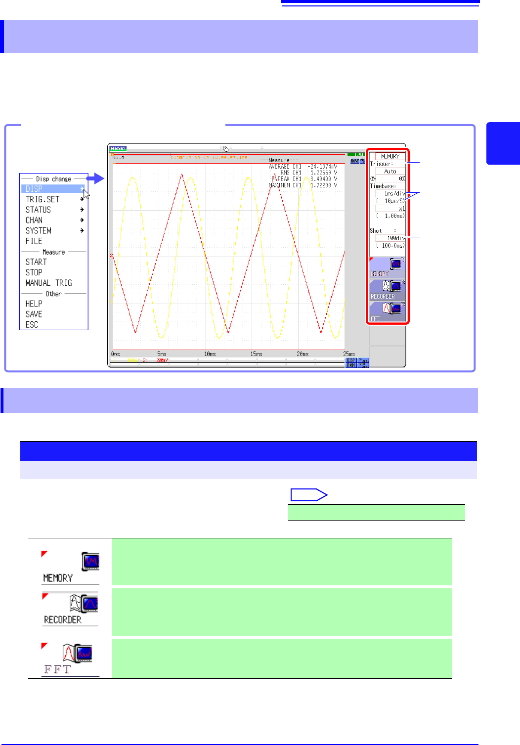
Set measurement conditions as follows.
By calling up the Waveform screen and then using the Settings window to make basic settings, you
can immediately verify the effect of settings on the waveform. Basic settings can also be made by
calling up the Status screen and selecting the [Status] sheet.
Select the function according to the measurement and recording target.
3.4 Setting Measurement Configuration
Settings window
(p.65)
Timebase
setting
(Sampling
rate)
(p.67)
Recording
Length
(Number of
divisions)
(p.70)
Opening the Settings window
Click [DISP] in the
right-click menu.
3.4.1 Measurement Function
Procedure
To open the screen: Right-click and select [DISP] Waveform screen
Move the flashing cursor to the function item (topmost field
in the settings window).
Select
MEMORY (default setting)/RECORDER/FFT
This function is most suitable for oscilloscope-type measurements,
such as instantaneous waveforms and transient phenomena.
Trigger functions and calculation functions can be used.
This function is suitable for use instead of pen recorders and pen oscil-
loscopes, to record long-term fluctuations and create records for
observing slow phenomena.
Real-time printing of data is possible.
Analyze the frequency.
Various types of spectrum and octave analysis can be performed.
See: "Chapter 12 FFT Function" (p.247)
3.4 Setting Measurement Configuration
66
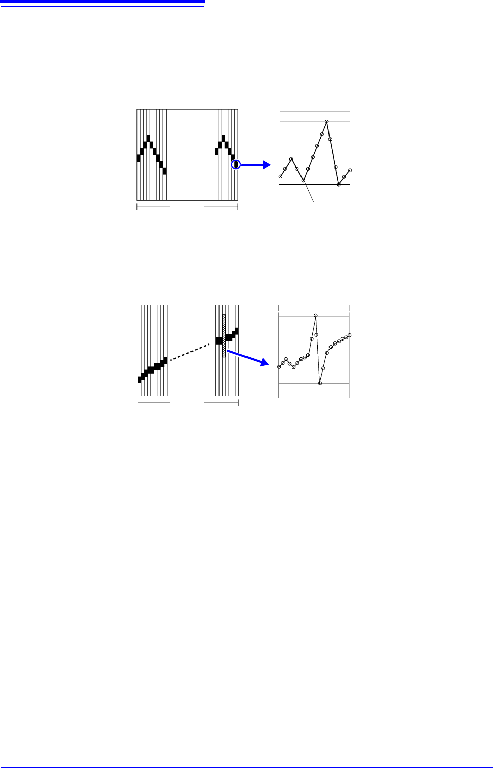
Description Recorder Function Values
With the Recorder function, each data sample consists of the maximum and min-
imum values acquired in the specified sampling period. So each data sample
has its own amplitude breadth.
When input waveform variation is slight, the difference between maximum and
minimum values (breadth, or width) can be inordinately large if the sampling
period is short and if severe fluctuations are present due to noise.
This phenomena may be prevented by setting a longer sampling period.
1 2 3 4........... ....100
1 div
Data of One Sample
Maximum value
Minimum value
Data acquired within the specified sampling period
1 2 3 4........... ....100
1 div
Data of One Sample
Maximum value
Minimum value
When the sampling period is short (fast)