MR8740、MR8741_user_manual_eng_20191016H.pdf - 第348页
16.1 Connecting External C ontrol Terminals (MR8741 Only) 336 The method for connecting to the extern al control terminals is as follows. 16.1 Connecting External Control T erminals (MR8741 Only) Connecting External I/O …
335
13
Chapter 16 External Control (MR8741 Only)
15
16
This chapter describes how to operate MR8741 using the external control terminals.
We use the term external control terminals generically to refer to all of the terminals.
External Control
(MR8741 Only) Chapter 16
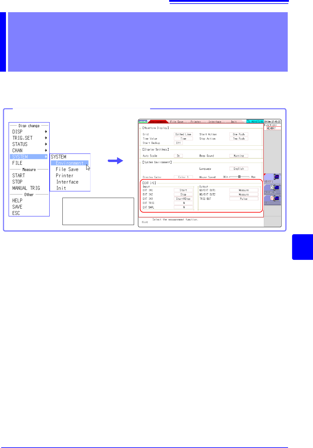
Opening the [Environment] sheet
Select [SYSTEM] and
then [Environment] from
the right-click menu.
16.1 Connecting External Control Terminals (MR8741 Only)
336
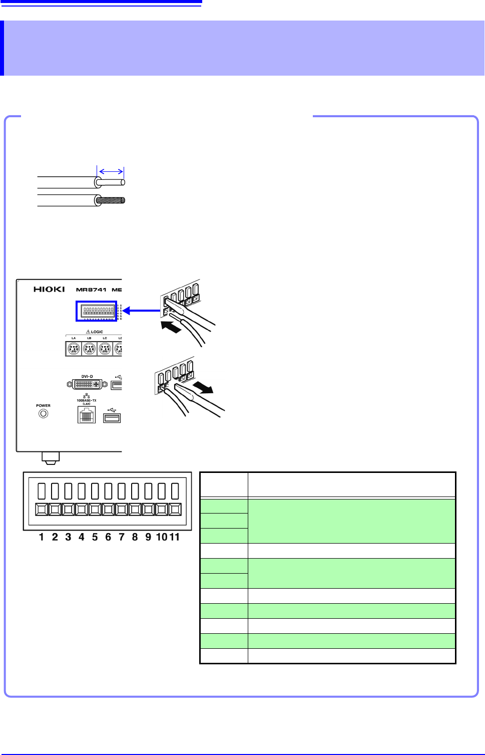
The method for connecting to the external control terminals is as follows.
16.1 Connecting External Control Terminals
(MR8741 Only)
Connecting External I/O Terminals (Connector Blocks)
Cables to connect
Recommended cables:
single strand diameter: 0.65 mm (AWG22)
multi-strand: 0.32 mm
2
(AWG22)
Usable cables:
Single strand diameter: 0.32 - 0.65 mm (AWG28 to 22)
Multi-strand: 0.08 - 0.32 mm
2
(AWG28 - 22)
Strand diameter: 0.12 mm or greater (per wire)
Standard insulation stripping length: 9 - 10 mm
Button operation specified tool: Flat-blade screwdriver (3 mm shaft diameter,
2.6 mm tip width)
Single strand
Multi-strand
10 mm
Connection procedure
1. Push in the button on the connector with a flat-
blade screwdriver or other tool.
2. With the button held in, insert the cable into the
cable connection hole.
3. Release the button.
The cable is locked.
1
2
3
EXT.TRIG
TRIG OUT
GND
SMPL
GND
NG/OUT2
GO/OUT1
GND
STOP/IN2
START/IN1
SAVE/IN3
Terminal
No.
Operation
1
Input external signal and execute the following
• Start/end measurement
• Save data
2
3
4-
5
Output instrument status as a signal
6
7-
8 Input external signal and set sampling rate
9-
10 Output signal when triggering occurs
11 Input external signal as trigger source
16.2 External I/O (MR8741 Only)
337
13
Chapter 16 External Control (MR8741 Only)
15
16
External control signals can be applied to start and stop measurement, and to save data. The fac-
tory-default settings are to [START], [STOP], and [SAVE].
1. Connect the cables for the corresponding external input signals to START/ IN1,
STOP/IN2, SAVE/IN3, and GND terminals.
See: "16.1 Connecting External Control Terminals (MR8741 Only)" (p.336)
2. On the SYSTEM screen, open the [Environment] sheet and move the cursor to
the [START/EXT.IN1], [STOP/EXT.IN2], or [SAVE/EXT.IN3] item.
3. Select the operation performed by the instrument in response to external signal input.
Select
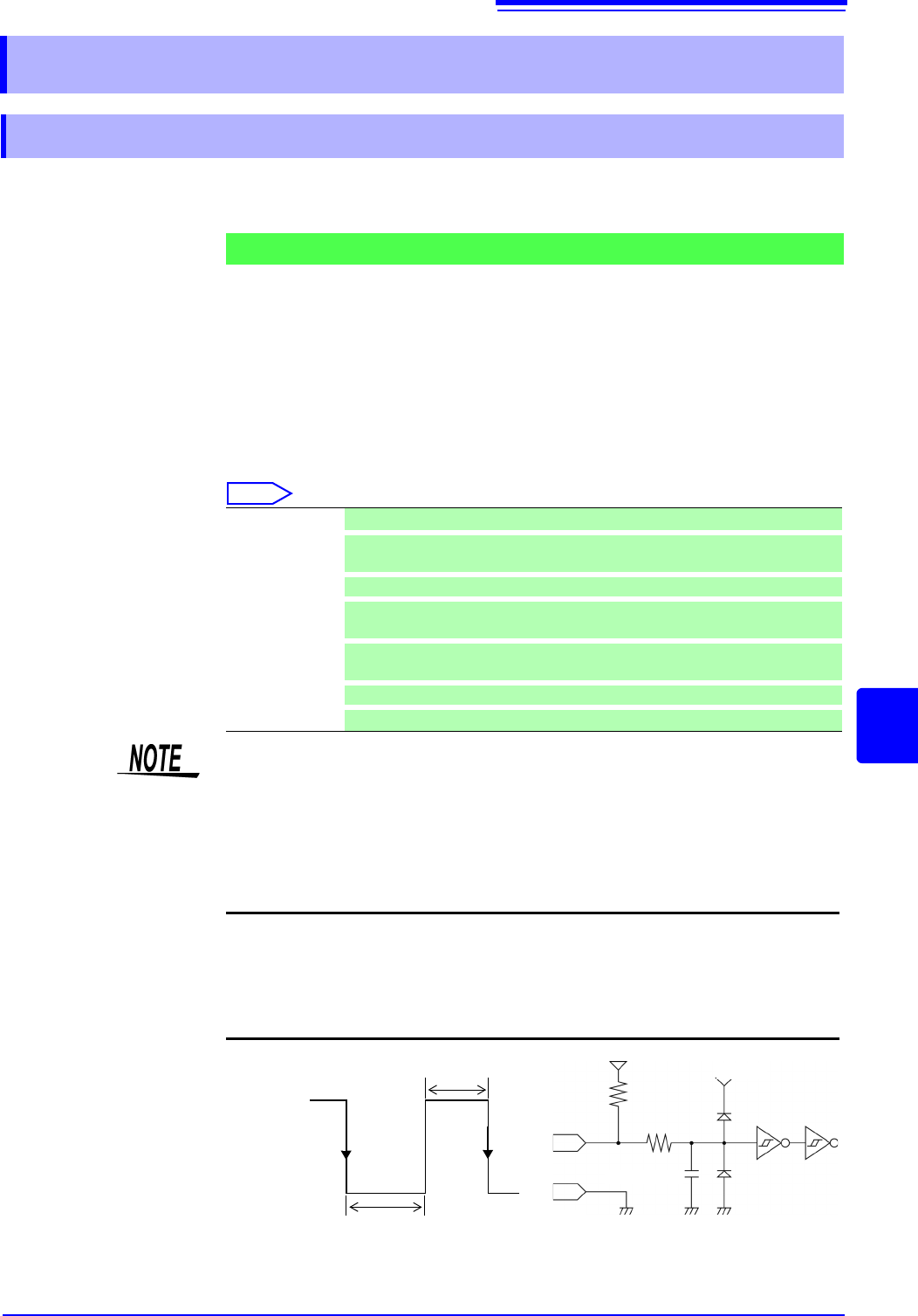
4. Short circuit the terminal and GND, or input a HIGH level (3.0 to 5.0 V) or LOW
level (0 to 0.8 V) pulse wave or rectangular wave to the terminal.
Control with the LOW level of the input waveform.
16.2 External I/O (MR8741 Only)
16.2.1 External Input (START/IN1) (STOP/IN2) (SAVE/IN3)
Signal Input Procedure
Start Start measurement. (Is not affected by [Start Action] (p.311))
Stop
Stop measurement. (Operations after measurement, such as numerical calcula-
tions and automatic saving will be carried out)
Start/Stop
Start measurement on LOW level, and stop measurement on HIGH level.
Abort
Stop measurement immediately. (Operations after measurement, such as nu-
merical calculations and automatic saving will not be carried out)
Save
Save the data according to the saving conditions specified on the [File Save]
sheet of the System screen. (Not valid during Selective Saving (p.93))
RUN/STOP
Runs/stops waveform output. (RUN at LOW level, STOP at HIGH level).
PAUSE
Stops waveform output temporarily.
• For STOP operation, follow [Stop Action] (p.311).
• External input is not available when the HELP screen or a dialog window is
being displayed.
Voltage range HIGH level: 3.0 to 5.0 V , LOW level: 0 to 0.8 V
Pulse width HIGH level: 20 ms or greater, LOW level: 30 ms or greater
Maximum input
voltage
-0.5 to 7 V
START/IN1
STOP/IN2
SAVE/IN3
470
GND
2200 pF
5 V
3.3 k
HIGH
3.0 to 5.0 V
LOW
0 to 0.8 V
30 ms or greater
20 ms or
greater
5 V