MR8740、MR8741_user_manual_eng_20191016H.pdf - 第145页
6.6 Monitoring Input Levels (L evel Monitor) 133 5 Chapter 6 W aveform Screen Monitoring and Analysis 6 Input values can be monitored as nu merical values in the same way as with a DMM (digital multim- eter). 6.6.2 Numer…
6.6 Monitoring Input Levels (Level Monitor)
132
All input waveform levels can be monitored in real time.
Analog channels and logic channels can be displayed at the same time.
6.6 Monitoring Input Levels (Level Monitor)
6.6.1 Level Monitor
Procedure
To open the menu: Right-click and select [DISP] Display Menu
Analog channel level
To hide the level monitor
Select [Monitor] again.
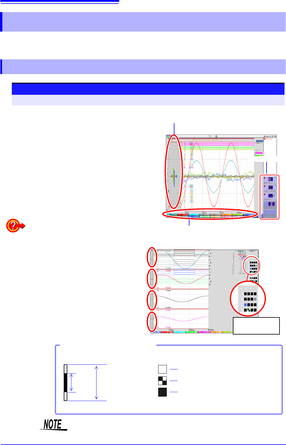
Selecting [Monitor] displays the analog channel level
on the left of the Waveform screen, the logic channel
level on the right of the Waveform screen, and the
monitor numerical values at the bottom of the Wave-
form screen.
Monitor values of analog channels
(Up to 6 digits are displayed.)
Display menu
Display format 2 - 16 screens (p.72)
Level monitors are displayed for each graph.
Upper and lower limit indication is combined with
level monitor.
See: "6.7.1 Showing Upper/Lower Limit On Waveform
Screen" (p.134)
Logic channel
level display
Level display of an analog channel
High
Hi gh& Low
Low
Input
Level
Waveform Display
Range Full Span
Level display of logic channels
How to View a Level Monitor
When the display setting is On,
the part indicated in white takes
the color specified for the wave-
form display. When the setting is
Off, the part becomes gray. The
part indicated in black takes the
background color.
Input levels are not displayed for channels having no corresponding module
installed.
6.6 Monitoring Input Levels (Level Monitor)
133
5
Chapter 6 Waveform Screen Monitoring and Analysis
6
Input values can be monitored as numerical values in the same way as with a DMM (digital multim-
eter).
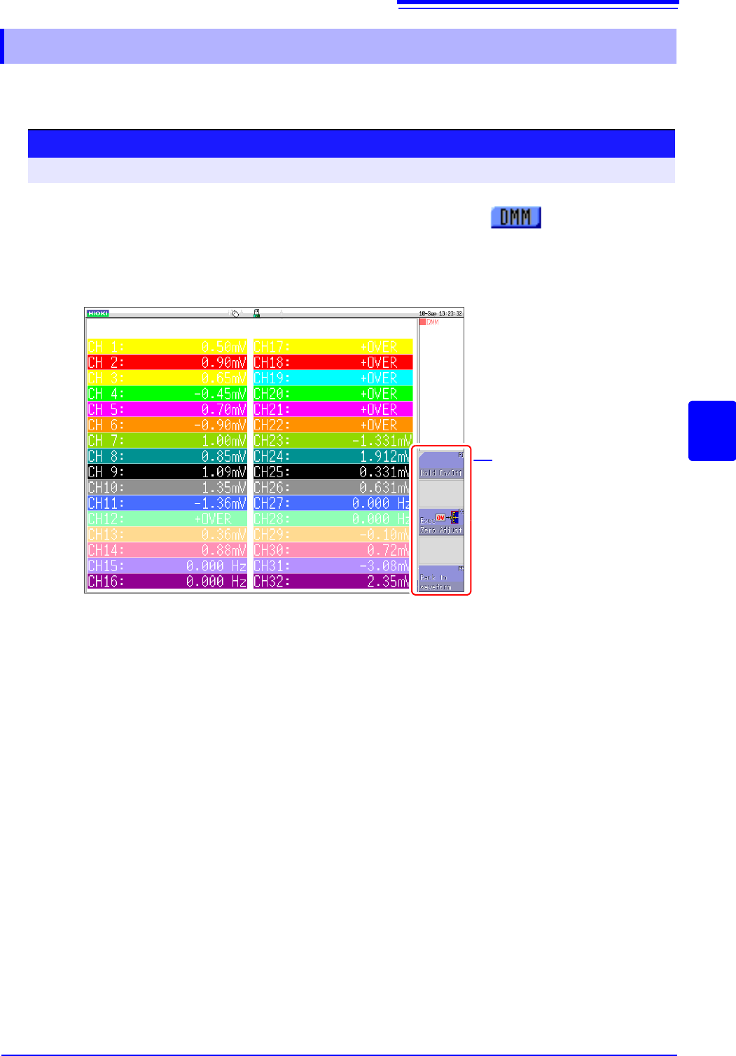
6.6.2 Numerical Value Monitoring (DMM Display)
Procedure
To open the screen: Right-click and select [DISP] Left-click the [DMM] icon
Left-click the [DMM] icon.
Left-click the [DMM] icon on the top right of the Waveform
screen.
The display changes to numerical value (DMM) display.
To return to the Waveform screen
Left-click [Back to waveform] in the display menu on the right of the
screen.
To pause (hold) display
Left-click [HOLD ON/OFF] in the display menu on the right of the screen.
The HOLD mark appears at the top of the screen to indicate that the
screen is in the HOLD state.
Click [HOLD ON/OFF] in the HOLD state to cancel hold.
Zero adjust
Zero adjustment (calibration for MR8990) can also be performed in the
numerical value (DMM) display screen. Left-click [Exec Zero-Adjust] in
the display menu on the right of the screen.
Display menu
6.7 Switching the Waveform Screen Display (Display Menu)
134
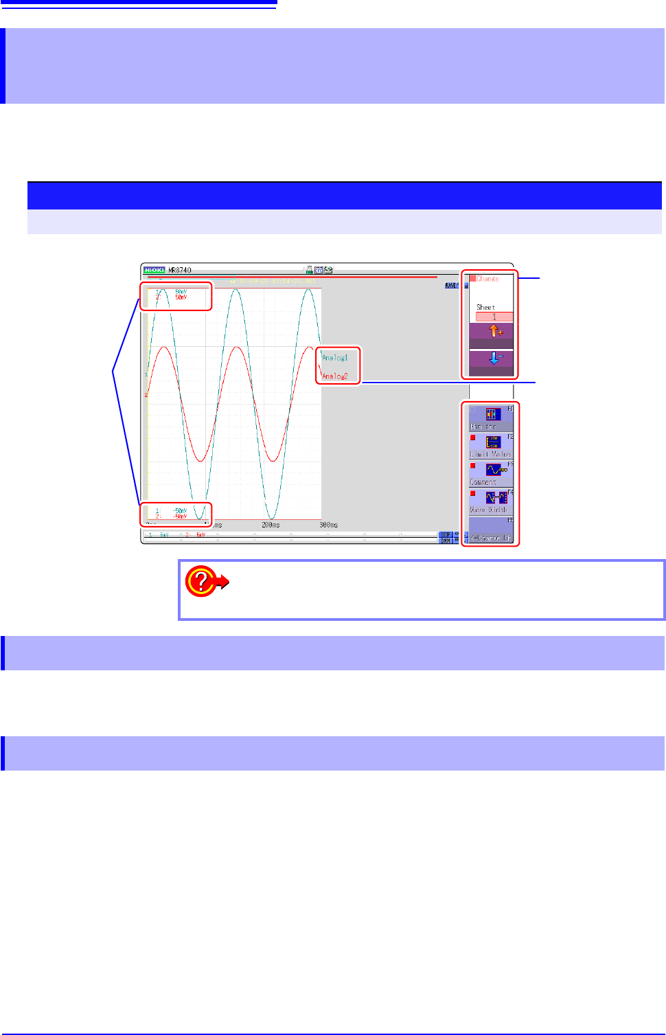
The display menu allows you to bring up additional information such as upper/lower limit value indi-
cation and comment display. It also allows you to set the waveform display width.
See: About level monitor (p.132)
Select [Limit Value] to show the upper/lower limit value indication on the Waveform screen.
Select [Comment] to show the comment indication on the Waveform screen.
• Comment information must have been entered via the [Comment] sheet on the Channel screen.
See:"7.1 Adding Comments" (p.138)
• When overlapped with other displayed elements, the comments may not display properly. Hide the Chan-
nel Settings Window, Trigger Settings Window, Level Monitor, etc., or decrease the [Wave Width].
6.7 Switching the Waveform Screen Display
(Display Menu)
Procedure
To open the menu: Right-click and select [DISP] Display Menu
Upper and Lower
Limit Value
Display Menu
Comment
Displayed sheet
switching
To hide the menu:
Select the same menu again.
6.7.1 Showing Upper/Lower Limit On Waveform Screen
6.7.2 Showing Comments On Waveform Screen