MR8740、MR8741_user_manual_eng_20191016H.pdf - 第163页
7.4 Converting Input Values (Scaling Function) 151 6 Chapter 7 Utility Functions 7 However, you may need to switch the vertical a xis (voltage axis) range to suit actual input values. For example, to display ±0.2 V at fu…
7.4 Converting Input Values (Scaling Function)
150
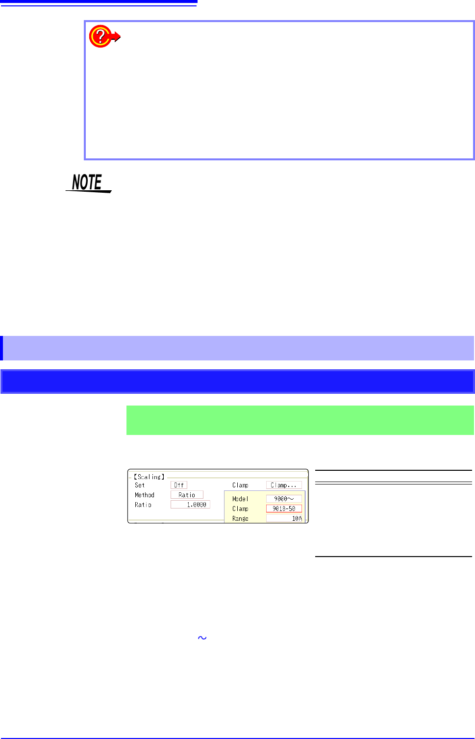
The 9018-50 Clamp On Probe provides 0.2 V output when measuring 10 A. So
Scaling should be set to display 10 A with 0.2 V input (and 0 A with 0 V input).
Selecting a Clamp Type ___________________________________________
1. Move the flashing cursor to the [Clamp] item, and select [Select].
The flashing cursor moves to the [Model] item.
2. Select [9000 ].
The flashing cursor moves to the [Clamp].
3. Select [9018-50] from the clamp list and select [Confirm].
Units, scaling method, and ratio are set automatically.
4. Select the same range of the clamp when using the range selection type.
Select [10A] here.
To reset Scaling settings:
Move the flashing cursor to the [Setting], and select [Reset].
To copy the scaling setting to another channel
The Channel screen - [Scaling] sheet can be used to copy a setting.
See: "7.8 Copying settings to other channels (calculation No.) (Copy function)" (p.160)
Using the Scaling and Variable functions (p.155) in combination:
The full span of output from a sensor can be displayed. (p.157)
At factory shipping, automatic correction of the variable function (p.311) is set to
[On].
At this time, the Variable setting is altered so that it is linked to (dependent upon)
the vertical axis (voltage axis) range and scaling settings. If you want the Vari-
able function setting to take priority, use either of the following procedures:
• Set Scaling first, and then set the Variable function
• Set a Variable value before Scaling, and then set Scaling.
When automatic correction of the Variable function (Variable Auto Adjustment) is
disabled ([Off]), the Scaling and Variable settings are unlinked (independent of
one another).
7.4.1 Scaling Setting Examples
Using a Clamp-On Probe
Example 1
Measure with the 10 A range of the Model 9018-50 Clamp On Probe and
display the measured data in units of [A] (Amperes)
Setting Items Setting Choice
Disp NUM or SCI
Clamp 9018-50
Unit
*
A
Method
*
Ratio
Ratio
*
50.000
*: Set automatically when clamp is selected.
7.4 Converting Input Values (Scaling Function)
151
6
Chapter 7 Utility Functions
7
However, you may need to switch the vertical axis (voltage axis) range to suit
actual input values.
For example, to display ±0.2 V at full scale, set the vertical display to 20 mV per
division (the instrument's 20 mV/div range)
For the rated capacity and rated output, consult the calibration record of the
strain gauge transducer to be used. Set as follows:
With scaling, signals from the sensor are
acquired as current values.
A/B cursors and gauges are displayed
with current (Ampere) values.
See: Upper/lower limit: (p.134)
Cursor A/B value: (p.120)
Before Scaling
After Scaling
[A]
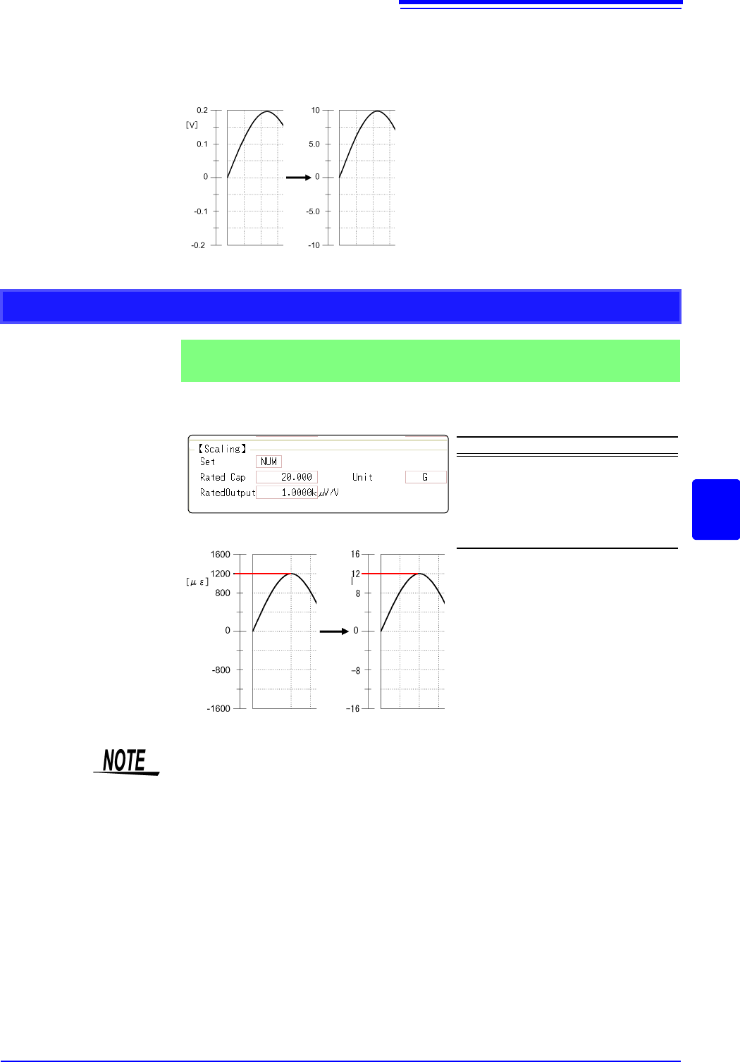
Using Model 8969 or U8969 Strain Unit
Example 2
Using the 20 G rated capacity and a strain gauge transducer with 1000
V/V rated output, display measured data in units of [G]
Setting Items Setting Choice
Disp NUM
Unit G
Rated Cap
(Rated capacity)
20 [G]
Rated Output 1k
By using the Scaling function, signals
from the strain gauge transducer are
acquired as physical values.
A/B cursors and gauges are displayed
as physical (G) values.
See: Upper/lower limit: (p.134)
Cursor A/B value: (p.120)
Before Scaling
After Scaling
[G]
Set the parameters such that the rated capacity divided by two times the rated output is
less than or equal to 9.9999
x 10
9
.
7.4 Converting Input Values (Scaling Function)
152
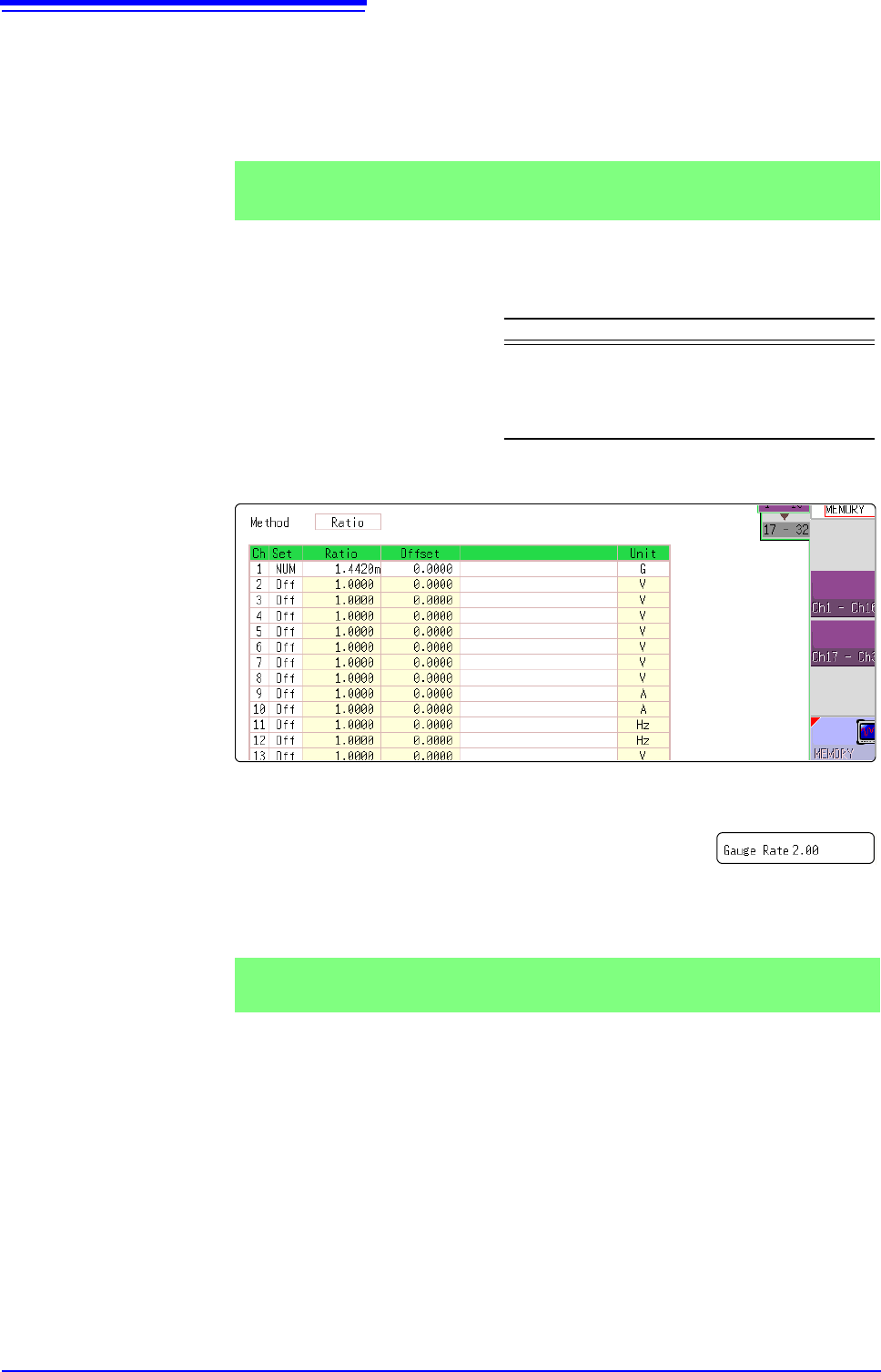
When a calibration factor is stated in the strain gauge transducer inspec-
tion records ________________________________________________________
Set the [Method] item on the [Scaling] sheet to [Ratio].
The value of the calibration factor (0.001442 [G]) is set as the conversion ratio.
(* 10
-6
strain = )
Move the flashing cursor to the channel to set, and making settings as follows.
Using a strain gauge with a Gauge Factor other than 2.0_______________
The 8969 or U8969 Strain Unit measures the Gauge Rate
as 2.0.
When using the other strain gauge, the Gauge Factor
needs to be set as the conversion ratio. For example, if the
Gauge Factor is 2.1, the conversion ratio is 0.952 (2
÷2.1).
The scaling (conversion ratio) needs to be calculated to include both Gauge Fac-
tor and physical value conversions. In this case, the conversion ratio setting is
the product of the conversion ratios of the Gauge Factor and measurement unit
scaling.
The Gauge Factor component of the conversion ratio is 0.952, and the physical
value component is 0.001442*
Conversion Ratio = 0.952 x 0.001442 = 0.0013728
As in Example 3, enter [0.0013728] as the conversion ratio.
* To convert measurement values to physical values when using a strain gauge,
calculate using the Young's modulus or Poisson's ratio of the measurement
Example 3
Measure using a strain gauge transducer with a calibration factor of
0.001442 G / 1 x 10
-6
strain
*
, and display the measured data in [G] units.
Setting Items Setting Choice
Disp NUM
Unit G
Ratio
(Conversion ratio)
0.001442 [G]
(displays as 1.4420m)
This value cannot be
changed.
Example 4
Measure using a strain gauge (2.1 Gauge Factor), and display the mea-
sured data in [G] units.