MR8740、MR8741_user_manual_eng_20191016H.pdf - 第159页
7.3 Displaying New Waveforms Over Past Waveforms (Overlay) 147 6 Chapter 7 Utility Functions 7 Description When the Overlay function is enabled ( [Auto] or [Manual] ). • The Roll Mode function (p.1 45) and Overlay functi…
7.3 Displaying New Waveforms Over Past Waveforms (Overlay)
146
This applies to the Memory function only.
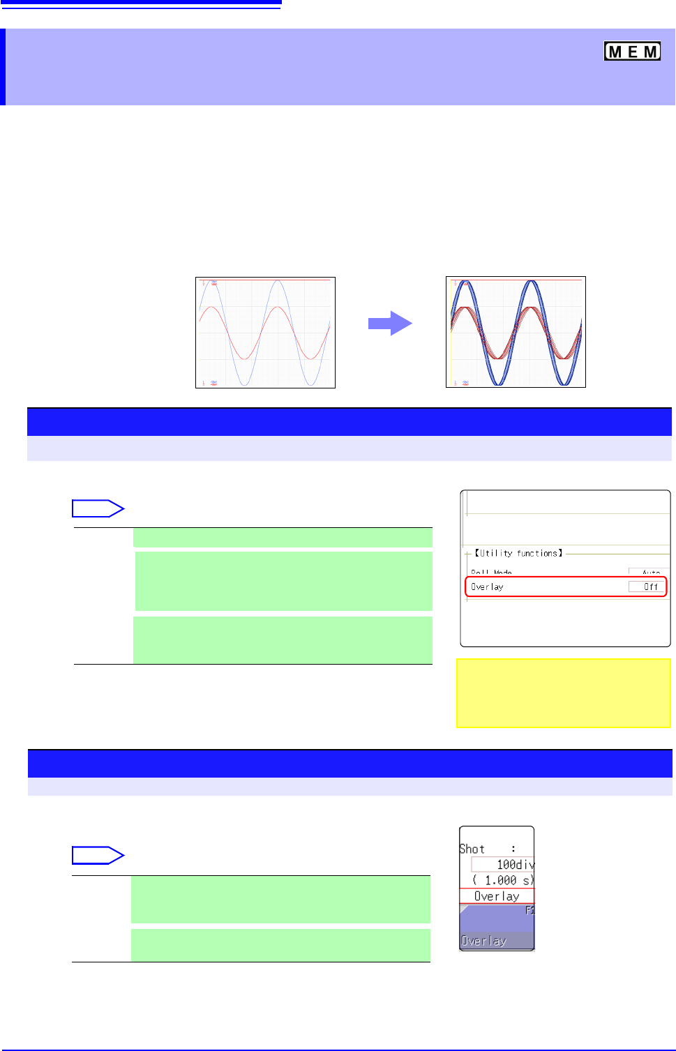
Displayed waveforms are retained on-screen and overlaid with new waveforms.
• Use this to compare new waveforms with those recorded immediately before.
(When the trigger mode is [Repeat] or [Auto]) (p.191)
• There are two overlay methods: automatic overlay during measurement and
manual overlay.
7.3 Displaying New Waveforms Over Past
Waveforms (Overlay)
Normal Display
Waveforms with the Overlay Function
Procedure
To open the screen: Right-click and select [STATUS] [Status] sheet
Move the flashing cursor to the [Overlay] item.
Select
Off Overlay disabled.(default setting)
Auto
Each time a waveform is acquired, it is automatically dis-
played as an overlay.
When the trigger mode is [Cont.] or [Auto], waveforms will
be overlaid from start until stop.
Manual
Overlay waveforms on the screen manually. Regardless of
the trigger mode, the waveform is left on the screen.
(
p.146)
This mode cannot be used simultaneously
with the Roll Mode.
"When the Overlay function is enabled
([Auto] or [Manual])." (
p.147)
Manual Overlay (Any waveform can be retained on-screen)
To open the screen: Right-click and select [DISP] Waveform screen
Move the flashing cursor to the [Overlay].
Select
Overlay Clicking [Overlay] leaves the loaded waveform on the
screen.
The overlay is displayed until the waveform is cleared.
Clear
Clears the screen of all overlaid waveforms.
Cleared waveforms cannot be displayed again.

7.3 Displaying New Waveforms Over Past Waveforms (Overlay)
147
6
Chapter 7 Utility Functions
7
Description When the Overlay function is enabled ([Auto] or [Manual]).
• The Roll Mode function (p.145) and Overlay functions (p.146) cannot both be
enabled at the same time. When the Roll Mode is enabled, the Overlay func-
tion is automatically set [Off]. And when Overlay function is enabled, automat-
ically turns the Roll Mode [Auto].
• The following operations are not available on the Waveform screen.
Waveform scrolling, Zoom function On/Off, Changing horizontal axis (time
axis) magnification/compression, Changing zero position
• In the following cases, overlaid waveforms are cleared and only the most
recent waveform is displayed.
• When [Format] was changed on the [Status] sheet
• When the [Combo Area] setting has been changed ([Format] set to [X-Y
Single] or [X-Y Quad])
• Waveform display setting was changed on [Unit List] sheet or [Each Ch]
sheet (Display magnification, zero position, variable, display on/off, wave-
form color)
7.4 Converting Input Values (Scaling Function)
148
About the Scaling
Function
Use the scaling function to convert the measured voltage units output from a sensor
to the physical units of the parameter being measurement.
Hereafter, "scaling" refers to the process of numerical value conversion using
the Scaling function.
Gauge scales, scale values (upper and lower limits of the vertical axis (voltage
axis)) and A/B cursor measurement values can be displayed in scaled units.
Scaling is available for each channel.
Scaling Setting Example
See: When using a clamp sensor (p.150) (Example: Converting [ V ] [ A ])
When using the Strain Unit (p.151) (Example: Converting [
] [ G ])
Scaling Methods Two scaling methods are available:
• Conversion Ratio Setting
• Two-Point Setting
7.4 Converting Input Values (Scaling Function)
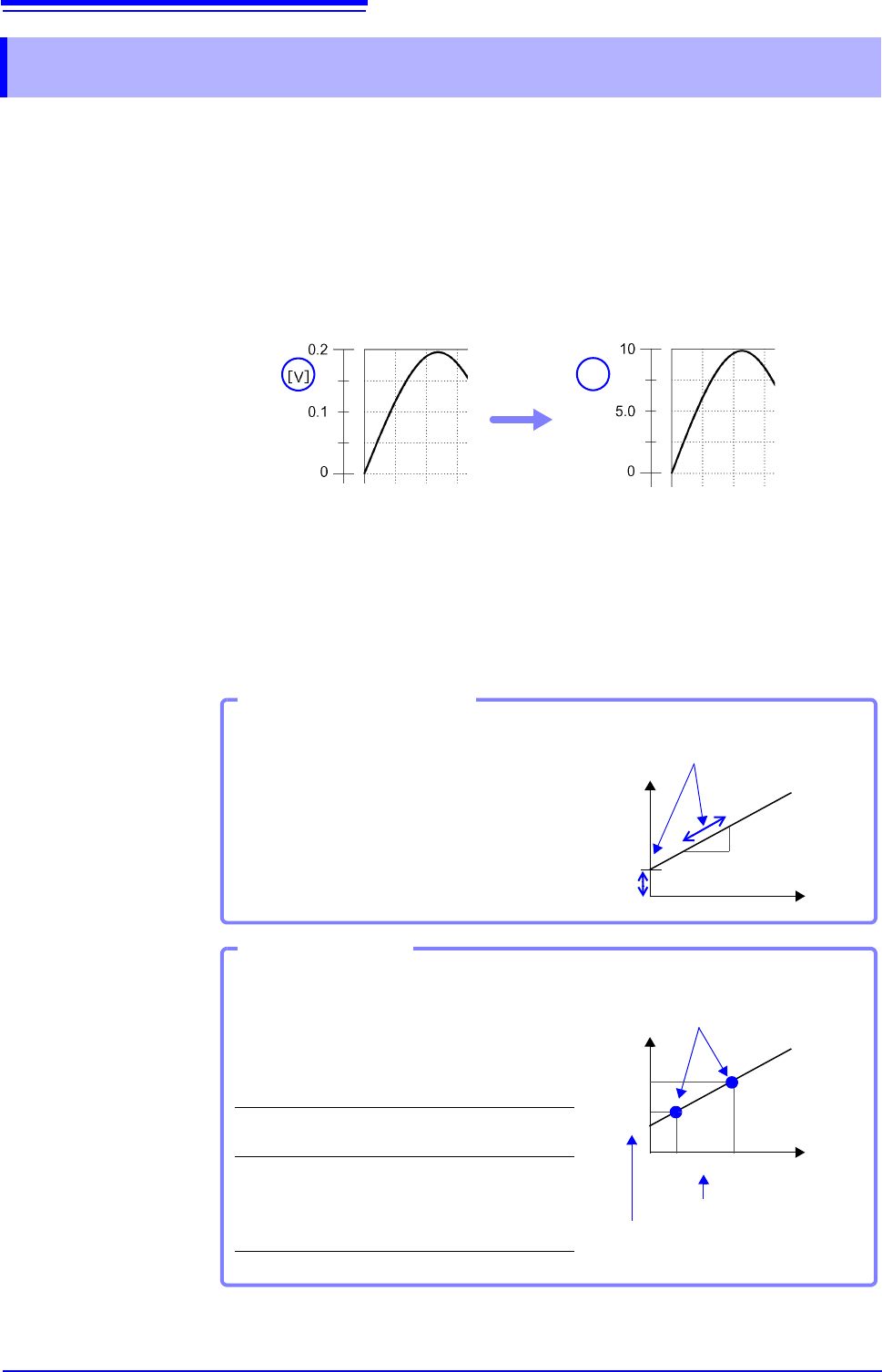
[A]
Before Scaling After Scaling
Set the physical value per volt (conversion ratio:
eu/V) of the input signal, an offset value and mea-
surement unit name (eu: engineering units) for
conversion, so measurement values acquired as
voltage are converted to the specified units.
Example:
Conversion ratio: A value per volt, Offset value:
B, Unit name: A
Conversion Ratio Setting
[A]
[V]
Convert from slope (conversion ra-
tio) and offset value
B
(:Example: Converting [V] [A])
Set the voltage values of two points of the input
signal, the converted unit value of these two
points and the name of the converted measure-
ment units, so measurement values acquired as
voltage are converted to the specified units.
Example:
Unit name: A
Voltage value at
2 points
Voltage of units to
convert
V
H
: Higher poten-
tial point
A
H
: Value for higher
potential point
V
L
: Lower poten-
tial point
A
L
: Value for lower
potential point
Two-Point Setting
A
H
A
L
V
L
V
H
[A]
[V]
Conversion ratio and offset value are
calculated from the two points and
converted
Actual measurement values
Converted unit values