MR8740、MR8741_user_manual_eng_20191016H.pdf - 第252页
10.3 Waveform Calculation Ope rators and Results 240

10.3 Waveform Calculation Operators and Results
239
9
Chapter 10 Waveform Calculation Functions
10
First integral (INT)
Second integral (INT2)
First and second integrals are calculated using the trapezoidal rule.
d
1
to d
n
are the integrals calculated for sample times t
1
to t
n
.
Calculation formulas for the first integral
Point t
1
I
1
= 0
Point t
2
I
2
= (d
1
+ d
2
)h/2
Point t
3
I
3
= (d
1
+ d
2
)h/2 + (d
2
+ d
3
)h/2 = I
2
+ (d
2
+ d
3
)h/2
Point t
n
I
n
= I
n-1
+ (d
n-1
+ d
n
)h/2
I
1
to I
n
: calculation results
h =
t: Sampling Period
Calculation formulas for the second integral
Point t
1
II
1
= 0
Point t
2
II
2
= (I
1
+ I
2
)h/2
Point t
3
II
3
= (I
1
+ I
2
)h/2 + (I
2
+ I
3
)h/2 = II
2
+ (I
2
+ I
3
)h/2
Point t
n
II
n
= II
n-1
+ (I
n-1
+ I
n
)h/2
II
1
to II
n
: calculation results
Digital Voltmeter Unit
PLC delay time shift
(PLCS)
Shifts the time by the amount of delay for the frequency (PLC) and NPLC set on MR8990
Digital Voltmeter Unit.
Since the Digital Voltmeter Unit obtains the average of the amount of time set for NPLC,
a waveform that is delayed by just a time that is 1/2 of the NPLC is observed, compared
to 8966 Analog Unit. The PLCS calculation shifts this amount of delay time to correct the
offset with the analog unit.
Reference: If there is no data at the end of the calculation result, the voltage becomes 0
V.
b
i
: ith member of calculation result data, d
i
: ith member of source channel data
Waveform Calculation Type Description

10.3 Waveform Calculation Operators and Results
240
241
10
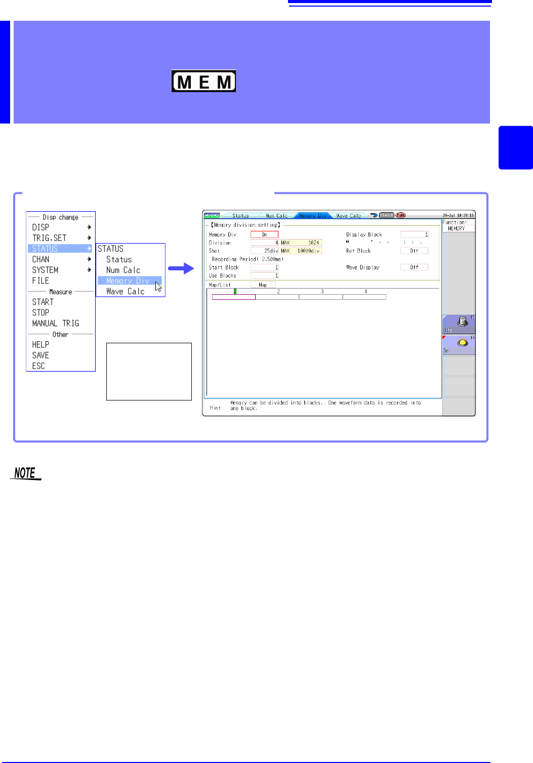
Chapter 11 Memory Division Function
11
Memory division function can only be used with the Memory function.
Memory division settings are made on the Status screen - [Memory Div] sheet.
Blocks to be displayed can also be selected on the Waveform screen (p.136).
Memory Division
Function Chapter 11
Opening the [Memory Div] sheet
Select [STATUS]
and then [Memory
Div] from the right-
click menu.
When using memory division, synchronization between blocks may not be possible in the following
conditions.
(MR8740 only)
When using memory division, the trigger output (TRIG_OUT terminal output) may output the Low
level or output erratically in the following conditions.
(MR8741 only)
• The time axis range is 5 s/div to 100 s/div
• The record (measurement) time is 5 ms or less
• Tracking wave display is [OFF].