MR8740、MR8741_user_manual_eng_20191016H.pdf - 第404页
Appendix 2 Reference A 8 *: If the data up date rate specified at NPLC is lon ger than the sampling r ate indicated in the table a bove, one of data is measur ed repeatedly during the data update rate period. See:"7…
Appendix 2 Reference
A7
Appendix
(d: days/ h: hours/ min: minutes/ s: seconds)
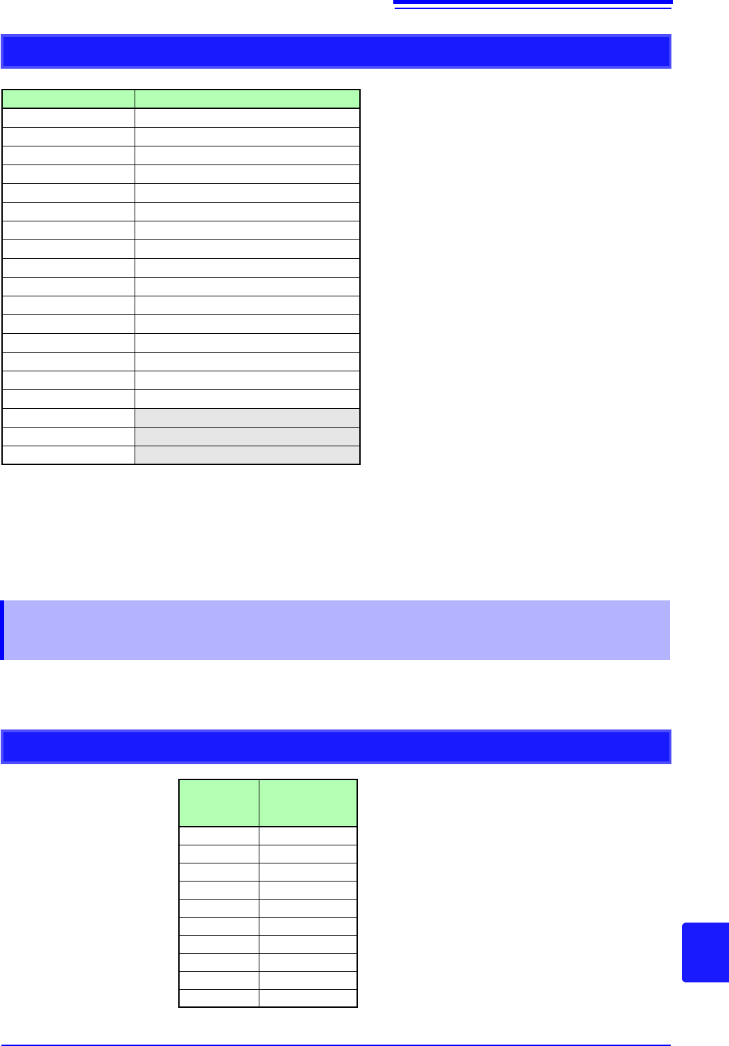
*: Also when recording length is set to [Cont.], the the maximum recording length is 80,000div.
The maximum record length is automatically determined by settings for the number of channels
used and the number of divisions.
Recorder Function
Timebase/div Maximum Recording Length : 80,000 div
*
10 ms 13 min 20 s
20 ms 26 min 40 s
50 ms 1 h 6 min 40 s
100 ms 2 h 13 min 20 s
200 ms 4 h 26 min 40 s
500 ms 11 h 6 min 40 s
1 s 22 h 13 min 20 s
2 s 1 d 20 h 26 min 40 s
5 s 4 d 15 h 6 min 40 s
10 s 9 d 6 h 13 min 20 s
30 s 27 d 18 h 40 min 0 s
50 s 46 d 7 h 6 min 40 s
1 min 55 d 13 h 20 min 0 s
100 s 92 d 14 h 13 min 20 s
2 min 111 d 2 h 40 min 0 s
5 min 277 d 18 h 40 min 0 s
10 min
30 min
1 h
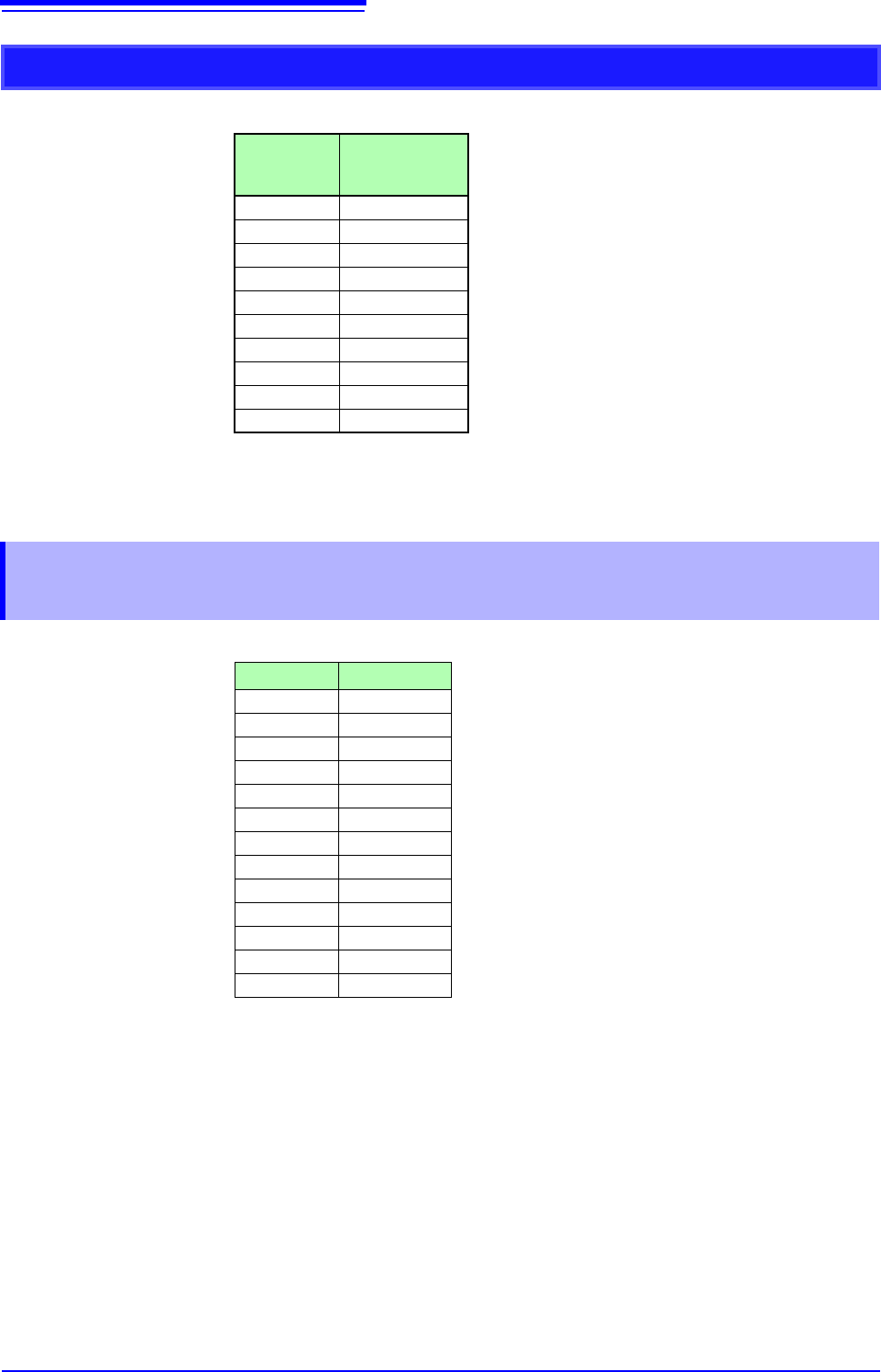
Appendix 2.4 Maximum record length and number of
divisions (Memory division function)
Desired record length
The number of
divisions
(blocks)
Maximum record
length (div)
2 80,000
4 40,000
8 20,000
16 10,000
32 5,000
64 2,500
128 1,200
256 600
512 300
1024 150
Appendix 2 Reference
A8
*: If the data update rate specified at NPLC is longer than the sampling rate indicated in the table above, one
of data is measured repeatedly during the data update rate period.
See:"7.9.8 Setting Model MR8990 Digital Voltmeter Unit" ( p.171)
*: If the time axis range is set to one faster than 100 ms/div, one of data is measured repeatedly during the
data update rate period specified at NPLC.
See:"7.9.8 Setting Model MR8990 Digital Voltmeter Unit" ( p.171)
Fixed record length
The number of
divisions
(blocks)
Maximum record
length (div)
250,000
420,000
820,000
16 10,000
32 5,000
64 2,000
128 1,000
256 500
512 200
1024 100
Appendix 2.5 Time Axis Range and Sampling Rate of
MR8990 Digital Voltmeter Unit
Timebase/div Sampling Rate
100 ms 2 ms
200 ms 4 ms
500 ms 10 ms
1 s 20 ms
2 s 40 ms
5 s 100 ms
10 s 200 ms
30 s 600 ms
50 s 1 s
1 min 1.2 s
10 s 2 s
2 min 2.4 s
5 min 6 s
Appendix 2 Reference
A9
Appendix
This section describes how to determine the scaling conversion ratio when measuring with strain
gauges and the Model 8969 and U8969 Strain Unit.
The appropriate conversion formula for stress depends on how the strain gauges
are used.
Three methods are available depending on whether one, two or four strain
gauges are used for measurement. The two-gauge method is used for tempera-
ture compensation.
E: Young modulus, : Poisson ratio, : Distortion measurement value
Tensile and Compressive Stress Measurement: Stress () = E ×
For temperature compensation with two or four gauges, position the gauges per-
pendicularly.
Stress () is obtained by 1 / (1 + ) for two gauges, and by 1 / {2 (1 + )} for four
gauges.
Bending Stress Measurement: Stress () = E
×
For temperature compensation with two or four gauges, stress () is obtained as
a multiple of ½ or ¼, respectively.
Torsional Stress Measurement: Stress () = E / {2 (1 + )} × (two-gauge case)
For the four-gauge case, it is half of that.
Refer to the strain gauge instruction manual for combinations of strain gauges
for each measurement.
Example. Measuring Compressive Stress
Using the one-gauge method for an aluminum measurement object having a
Young's modulus of 73 (GPa) according to the following Table,
= 73 × 10
9
× Measurement Value (in units) × 10
-6
(in units)
) = 73 × Measurement Value (in kPa units)
= 7.44
*
× Measurement Value (in gf/mm
2
units)
*:
1 Pa = 1.01971621× 10
-7
kgf/mm
2
Unit: gf/mm
2
, Conversion Ratio = 7.44 gf/mm
2
Enter this value as the scaling conversion ratio
See: "7.4 Converting Input Values (Scaling Function)" (p.148)
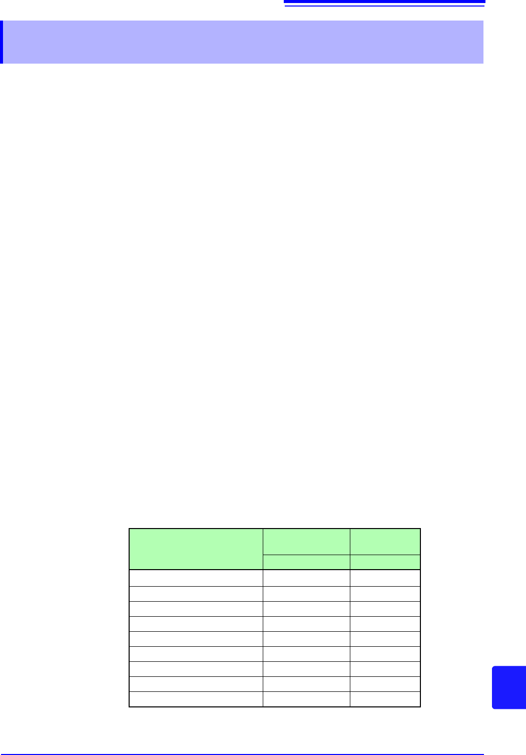
Appendix 2.6 Scaling Method When Using Strain
Gauges
Mechanical properties of industrial materials
Material
Modulus of Elasticity
(Young's Modulus)
Poisson's Ratio
E (GPa)
Carbon Steel (0.1 to 0.25% C)
205 0.28 to 0.3
Carbon Steel (> 0.25% C) 206 0.28 to 0.3
Spring Steel (Quenched) 206 to 211 0.28 to 0.3
Nickel Steel 205 0.28 to 0.3
Cast Iron 98 0.2 to 0.29
Brass (Cast) 78 0.34
Phosphor Bronze 118 0.38
Aluminum 73 0.34
Concrete 20 to 29 0.1