MR8740、MR8741_user_manual_eng_20191016H.pdf - 第407页
Appendix 3 About Options A 11 Appendix Module (for generation) These modules can be installed along with a measurement module. Application Model Number of channels Maximum output frequency Output voltage Arbitrary wavefo…
Appendix 3 About Options
A10
The following options are available for the instrument. Contact your authorized Hioki distributor or
reseller when ordering. The options are subject to change. Visit our website for updated information.
For details of cables and clamps for connecting to the modules and the instrument, refer to manual
supplied with them.
Items indicated "specify when ordering" are not user-installable. For new purchases, contact your supplier
(agent) or nearest Hioki office.
Appendix 3 About Options
Appendix 3.1 Options
Modules (Measurement amplifiers)
These are installed by insertion into the compartments on the right side of the instrument. Modules can be swapped out as
needed.
Application Model Channels
Max Sampling
Rate
A/D
Resolution
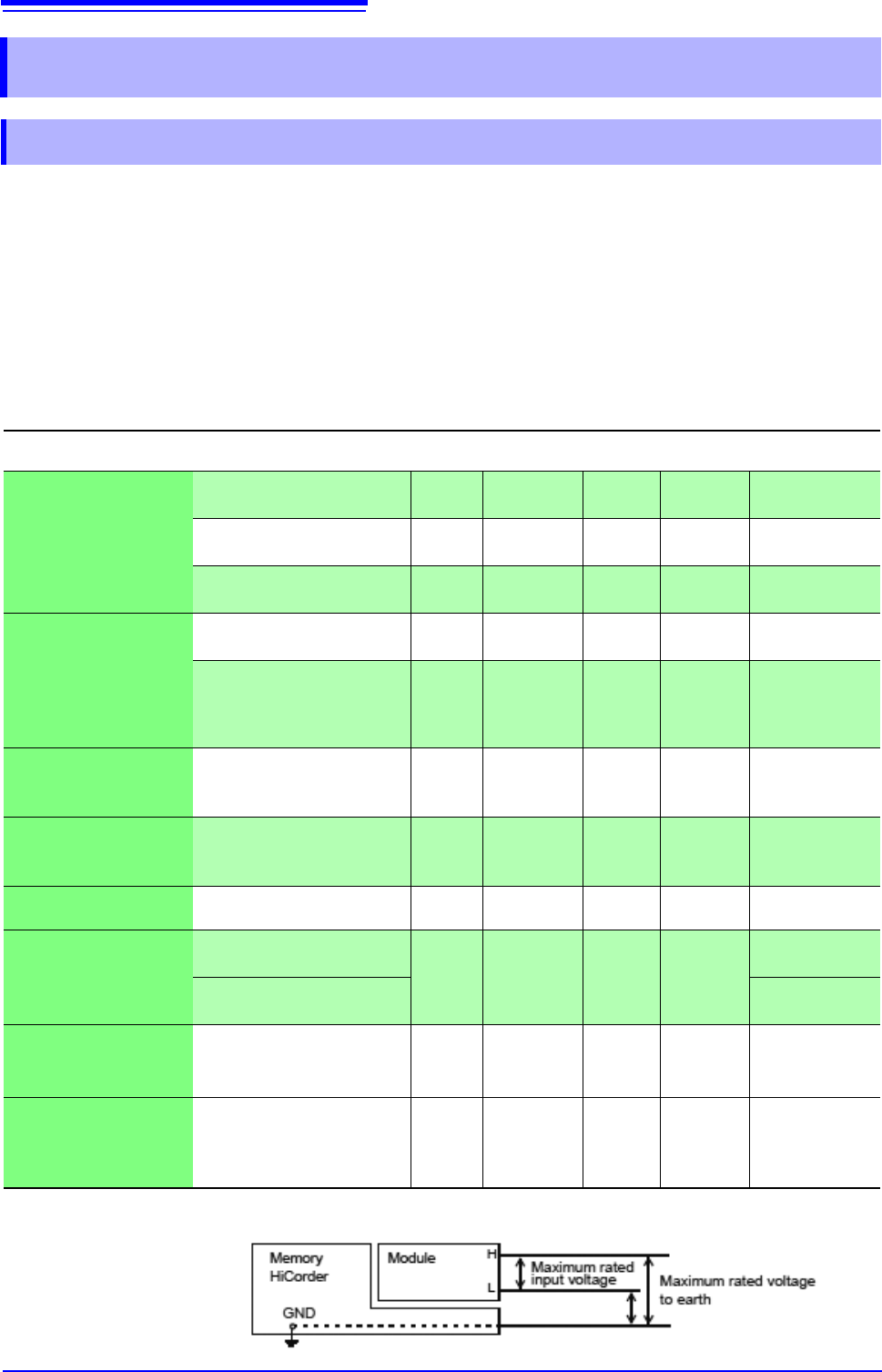
Maximum
input voltage
Maximum rated
voltage to earth
Voltage
measurements
Model 8966 Analog Unit
2 20 MS/s 12 bits 400 V DC
300 V AC, DC
(CAT II)
Model 8968 High Resolution
Unit
2 1 MS/s 16 bits 400 V DC
300 V AC, DC
(CAT II)
Model MR8990 Digital
Voltmeter Unit
2 500 S/s 24 bits 500 V DC
300 V AC, DC
(CAT II)
RMS voltage
measurements
Model 8972 DC/RMS Unit 2 1 MS/s 12 bits 400 V DC
300 V AC, DC
(CAT II)
Model U8974 High Volteage
Unit
2 1 MS/s 16 bits
1000 V DC
700 V AC
1000 V AC, DC
(CAT III)
600 V AC, DC
(CAT IV)
Temperature
(Thermocouple)
measurements
Model 8967 TEMP Unit 2 - 16 bits -
300 V AC, DC
(CAT II)
Frequency, count,
pulse duty, and pulse
width measurements
Model 8970 Freq Unit 2 - 16 bits 400 V DC
300 V AC, DC
(CAT II)
Current Measurement
(model 8741 only)
Model 8971 Current Unit 2 1 MS/s 12 bits -
Not insulated
Strain (Strain gauge
type converter)
measurements
Model 8969 Strain Unit
2 200 kS/s 16 bits -
33 V rms AC or
70 V DC
Model U8969 Strain Unit
30 V rms AC or
60 V DC
Digital signals
and contact signal
measurement
Model 8973 Logic Unit 16 20 MS/s - -
Not insulated
Acceleration measure-
ment (sensor with built-
in preamplifier, charge-
output sensor)
Model U8979 Charge Unit 2 200 kS/s 16 bits 40 V DC
30 V AC,
60 V DC
See: "17.6 Specifications of Modules" (p.352)

Appendix 3 About Options
A11
Appendix
Module (for generation)
These modules can be installed along with a measurement module.
Application Model
Number of
channels
Maximum output
frequency
Output voltage
Arbitrary waveform generation
U8793 Arbitrary Waveform Generator Unit 2 100 kHz -10 V to 15 V
Sine wave and DC generation
MR8790 Waveform Generator Unit 4 20 kHz ±10 V
Pulse generation
MR8791 Pulse Generator Unit 8 100 kHz 0 to 5 V
Measurement probes, cords, and clamps
Application Model Description
Maximum
input voltage
Mximum rated
voltage to earth
Voltage
measurement
Model L9197 Connection
Cord
For high voltage 600 V AC, DC
600 V AC, DC
(CAT III)
300 V AC, DC
(CAT IV)
Model L9198 Connection
Cord
For low voltage
300 V AC, DC 600 V AC, DC
Model L9790 Conection Cord 600 V AC, DC
600 V AC, DC
(CAT III)
300 V AC, DC
(CAT IV)
Model L9217 Connection
Cord
Isolated BNC-BNC 300 V AC, DC -
Model 9322 Differential Probe
For high voltage
• Model 9418-15 AC Adapter is
required when connecting to the
module for voltage measure-
ment.
2000 V DC,
1000 V AC
(CAT II)
600 VAC, DC
(CAT III)
-
Model P9000-01 Differential
Probe
Model P9000-02 Differential
Probe
The Model Z1008 AC Adapter or a
commercially available USB cable
is required.
1000 VAC, DC
(CAT III)
-
Model 9665 10:1 Probe
Maximum rate voltage above
ground is that of the module.
1 kV rms
(up to 500 kHz)
-
Model 9666 100:1 Probe
Maximum rate voltage above
ground is that of the module.
5 kVpeak
(up to 1 MHz)
-
Model 9166 Connection Cord
For inputting voltage to Model
U8979
30 V AC,
60 V DC
-
Logic signal input
Model 9320-01 Logic Probe
Four channels, for detecting volt-
age and closed/open contact
points
- -
Model MR9321-01 Logic
Probe
Four isolated channels, for detect-
ing AC/DC voltage on/off (for small
terminal types and for lines)
High range
250 V rms
Low range
150 V rms
250 V rms
(CAT II)
Model 9327 Logic Probe
Four channels, for detecting volt-
age and closed/open contact
points (high-speed type)
- -

Appendix 3 About Options
A12
Application Model Description
AC/DC
The CT955x or 9318 Conversion
Cable are required for connection.
Model 9709 AC/DC Current Sensor 500 A, DC to 100 kHz
Model CT6841 AC/DC Current Probe 20 A, DC to 1 MHz
Model CT6843 AC/DC Current Probe 200 A, DC to 500 kHz
Model CT6844 AC/DC Current Probe 500 A, DC to 200 kHz
Model CT6845 AC/DC Current Probe 500 A, DC to 100 kHz
Model CT6846 AC/DC Current Probe 1000 A, DC to 20 kHz
Model CT6862 AC/DC Current Sensor 50 A, DC to 1 MHz
Model CT6863 AC/DC Current Sensor 200 A, DC to 500 kHz
Model CT6865 AC/DC Current Sensor 1000 A, DC to 20 kHz
Dedicated for AC
The CT955x or 9318 Conversion
Cable are required for connection.
Model 9272-10 Clamp On Sensor 20 A/200 A, 1 Hz to 100 kHz
Dedicated for AC
Model 9018-50 Clamp On Probe 10 A to 500 A, 40 Hz to 3 kHz
Model 9132-50 Clamp On Probe 20 A to 1000 A, 40 Hz to 1 kHz
Leakage current
Model 9657-10 Clamp On Leak Sensor 10 A AC (Leakage current, 50 Hz/60 Hz)
Others
For connecting to a module for
voltage measurement
Model CT9555, CT9556, and CT9557
Sensor Unit
For Model 9272-10, 9709, CT6841,
CT6843, CT6844, CT6845, CT6846,
CT6862, CT6863, CT6865
For connecting to the Model
8971 Current Unit
Model 9318 Conversion Cable
For Model 9272-10, 9709, CT6841,
CT6843, CT6844, CT6845, CT6846,
CT6862, CT6863, CT6865
For more information on the output rate of a clamp sensor, see the indication on each clamp sensor or the instruction manual.
Software
Application Software
9333 LAN Communicator
9335 Wave Processor