MR8740、MR8741_user_manual_eng_20191016H.pdf - 第29页
1.2 Names and Functions of Parts 17 1 Chapter 1 Overview MR8741 Rear V arious Modules (p.36), (p.39) (For details, see the instruc- tion manual of the respective module.) 100BASE-TX Connector Connect a LAN cable here. (p…
1.2 Names and Functions of Parts
16
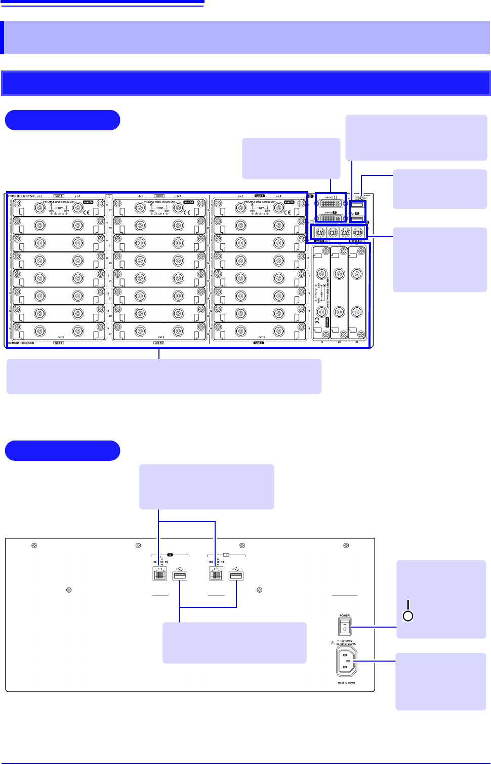
1.2 Names and Functions of Parts
MR8740
Front
Rear
Various Modules (p.36), (p.39)
(For details, see the instruction manual of the respective module.)
Power Inlet
Connect the supplied
power cord here.
(p.55)
POWER Switch
Turns the instru-
ment on and off.
: Power On
: Power Off
(p.56)
100BASE-TX Connector
Connect LAN cables here.
(p.313)
DVI-D Connectors
Connect an LCD
monitor here.
Standard LOGIC
Terminals
Input connectors for
optional logic probes.
(p.39)
USB Connector (Type A)
Connect USB memory sticks here.
(p.53)
Power Indicator
Lit when the instru-
ment is on.
USB Connector (Type A)
Connect USB memory sticks here.
(p.53)
1.2 Names and Functions of Parts
17
1
Chapter 1 Overview
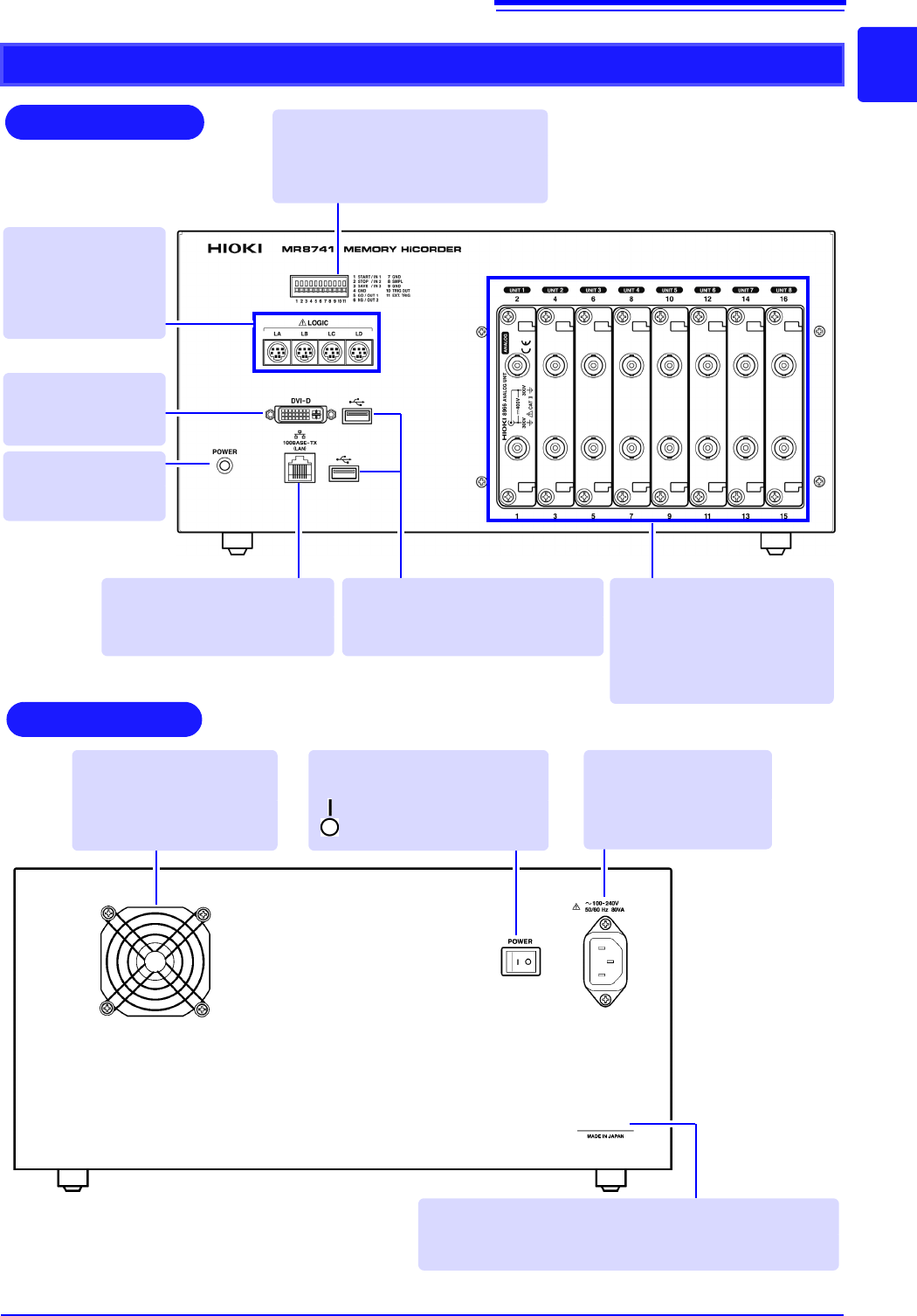
MR8741
Rear
Various Modules
(p.36), (p.39)
(For details, see the instruc-
tion manual of the respective
module.)
100BASE-TX Connector
Connect a LAN cable here.
(p.313)
Standard LOGIC
Terminals
Input connectors for
optional logic probes.
(p.39)
Power Indicator
Lit when the instru-
ment is on.
DVI-D Connector
Connect an LCD
monitor here.
USB Connector (Type A)
Connect USB memory sticks here.
(p.53)
Manufacturer's Serial No.
*
Shows the serial number.
Required for production control. Do not peel off the label.
POWER Switch
Turns the instrument on and off.
: Power On
: Power Off (p.56)
Power Inlet
Connect the supplied
power cord here.
(p.55)
Ventilation Holes (Fan)
Make sure the ventilation
holes are not obstructed.
Front
External control terminals
Input any external sampling signal
here. (p.336)
Allows control of the instrument.
*: The serial number consists of 9 digits. The first two
(from the left) indicate the year of manufacture, and
the next two indicate the month of manufacture.
1.3 Display
18
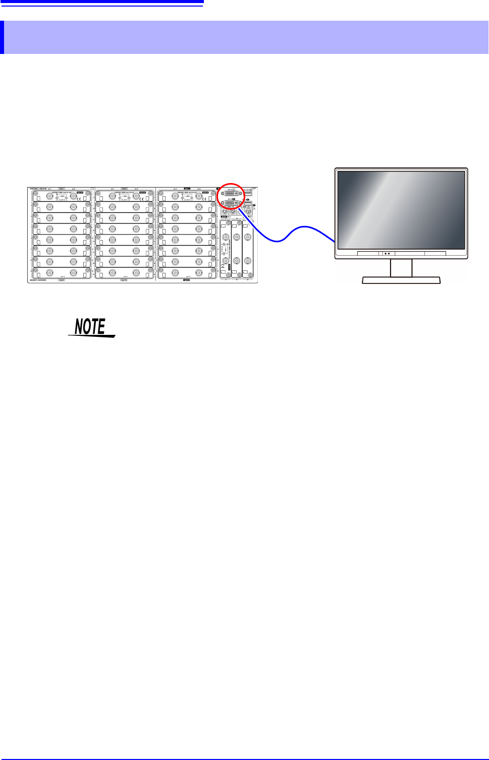
This instrument allows you to use a commercially available LCD monitor for displaying waveforms
and various settings.
1.3 Display
• The instrument’s DVI connectors are designed exclusively for digital. They
cannot be used for analog.
A VGA-DVI adapter also cannot be used.
• There are a variety of LCD monitors available, and not all LCD monitors will
work with the instrument.
• The display aspect ratio for DVI output with this instrument is 4:3. If you use a
wide LCD (16:9), display will be stretched in the horizontal direction.
• External interference may cause display to be distorted. Keep the LCD and
LCD cable as far away as possible from sources of interference.
• MR8740 displays the waveforms of the block I side (32 analog channels + 8
logic channels) with DVI-I, and the waveforms of the block II side (22 analog
channels + 8 logic channels) with DVI-II. The waveforms of block I and block II
cannot be displayed at the same time.
Connect the LCD monitor to a DVI-D connector on the front of the instrument.