MR8740、MR8741_user_manual_eng_20191016H.pdf - 第52页
2.2 Connecting Cords 40 Example: 8966 Analog Unit Required item: One of the above cables BNC jack Connect to BNC jack Lock Bayonet rugs on the module BNC plug slots Connect to the measurement object Connecting the cable …
2.2 Connecting Cords
39
2
Chapter 2 Measurement Preparations
Read "Before Connecting Cables" ( p.11) carefully.
For detailed precautions and instructions regarding connections, refer to the instruction manuals for your
modules, connection cables, etc.
2.2 Connecting Cords
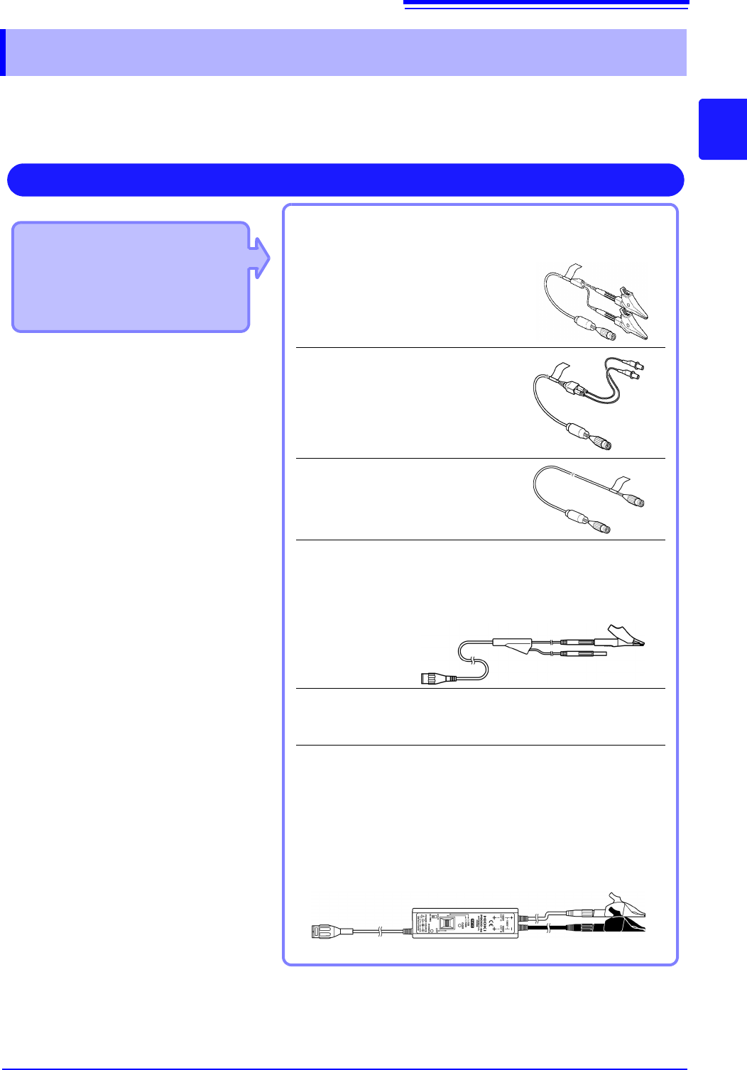
Applicable Modules
• 8966 Analog Unit
• 8968 High Resolution Unit
• 8972 DC/RMS Unit
• U8979 Charge Unit
Use to connect: Connection cords
• L9197 Connection Cord
(Maximum input voltage: 600 V)
Large alligator clip type
• L9198 Connection Cord
(Maximum input voltage: 300 V)
Small alligator clip type
• L9217 Connection Cord
(Maximum input voltage: 300 V)
For measuring BNC output
• L9790 Connection Cord
(Maximum input voltage: 600 V)
Terminal type: Alligator, contact, grabber
Example: Terminal type: Alligator
• 9166 Connection Cord
(Maximum input voltage: 30 V AC, 60 V DC)
Electrical clips
When a voltage to be measured exceeds a maximum input rating
of a module being used
• Model 9322 Differential Probe
*1
• Model 9665 10:1 Probe
• Model 9666 100:1 Probe
• Model P9000-01/-02 Differential Probe
*2
Example: Model P9000-02 Differential Probe
Measuring Voltage
Connect to the BNC jack on a module.
*1 An optional power cord or AC adapter is
required.
*2 An optional AC adapter or a commercially
available USB cable is required.
2.2 Connecting Cords
40
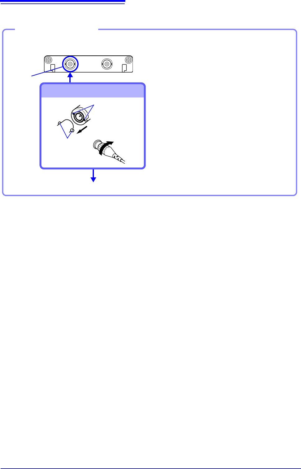
Example: 8966 Analog Unit
Required item: One of the above cables
BNC jack
Connect to BNC jack
Lock
Bayonet rugs on
the module
BNC plug slots
Connect to the measurement object
Connecting the cable
1
Connect the BNC plug on the cable to
a BNC jack on the module.
2
Align the slots in the BNC plug with
the guide pins on the jack on the mod-
ule, then push and twist the plug
clockwise until it locks.
3
Connect the cable clips to the mea-
surement object.
Disconnecting BNC connectors
Push the BNC plug, twist it counter-
clockwise, and pull it out.
2.2 Connecting Cords
41
2
Chapter 2 Measurement Preparations
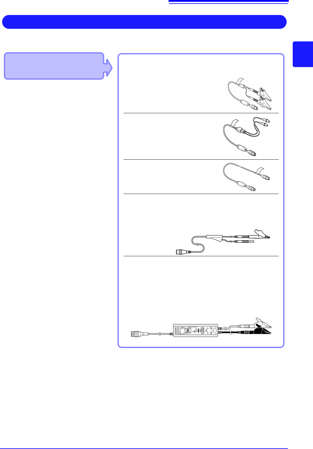
Applicable Modules
• Model 8970 Freq Unit
Use to connect: Connection cords
• L9197 Connection Cord
(Maximum input voltage: 600 V)
Large alligator clip type
• L9198 Connection Cord
(Maximum input voltage: 300 V)
Small alligator clip type
• L9217 Connection Cord
(Maximum input voltage: 300 V)
For measuring BNC output
• IModel L9790 Connection Cord
(Maximum input voltage: 600 V)
Terminal type: Alligator, contact, grabber
Example: Terminal type: Alligator
IIf the voltage to be measured exceeds the maximum input rating
of the module being used
• Model 9322 Differential Probe
*1
• Model 9665 10:1 Probe
• Model 9666 100:1 Probe
• Model P9000-01/-02 Differential Probe
*2
Example: Model P9000-02 Differential Probe
Measuring Frequency, Number of Rotations and Count
Connect to the BNC jack on a module.
*1 An optional power cord or AC adapter is re-
quired.
*2 An optional AC adapter or a commercially
available USB cable is required.
Refer to (p.40) for details about connecting to BNC terminals.