MR8740、MR8741_user_manual_eng_20191016H.pdf - 第189页
7.9 Setting Details of Modules 177 6 Chapter 7 Utility Functions 7 Channels ins talled with Model MR 8790 cannot be me asured. See: "Opening the [Each Ch] sheet, Making a Channel Sele ction" (p.161) Ty p e Sele…
7.9 Setting Details of Modules
176
When using an out-of-setting-range current sensor
You can use an out-of-setting-range current sensor using the scaling function.
See: "4.2.2 Automatically Saving Waveforms" (p.88)
Sensitivity Multiply the sensor sensitivity of a sensor to be used by a certain value to allow a
product to fall within the setting range (0.1 to 10), and enter the product.
Scaling Configure the scaling setting so that a scaling ratio is the same value as the
number you multiplied the sensor sensitivity by.
Example 1 For sensor sensitivity of 23.4 pC/(m/s
2
)
Specify 10 pC/(m/s
2
), which results from multiplying the sensor sensitivity by
1/2.34, as the sensor sensitivity.
To display measured values after multiplying them by 1/2.34, configure the scal-
ing setting as follows:
To configure the scaling setting using the conversion ratio method
To configure the scaling setting using the 2-point method
Example 2 For sensor sensitivity of 0.05 pC/(m/s
2
)
Specify 0.1 pC/(m/s
2
), which results from multiplying the sensor sensitivity by
two, as the sensor sensitivity.
To display measured values after multiplying them by two, configure the scaling
setting as follows:
To configure the scaling setting using the conversion ratio method
To configure the scaling setting using the 2-point method
Ratio 0.4274E+00 (= 10/23.4)
Offset 0.0000E+00
Units m/s
2
Input1 2.3400E+00 Scale1 1.0000E+00
Input2 0.0000E+00 Scale2 0.0000E+00
Units m/s
2
Ratio 2.0000E+00 (= 0.1/0.05)
Offset 0.0000E+00
Units m/s
2
Input1 0.0500E+00 Scale1 1.0000E+00
Input2 0.0000E+00 Scale2 0.0000E+00
Units m/s
2
7.9 Setting Details of Modules
177
6
Chapter 7 Utility Functions
7
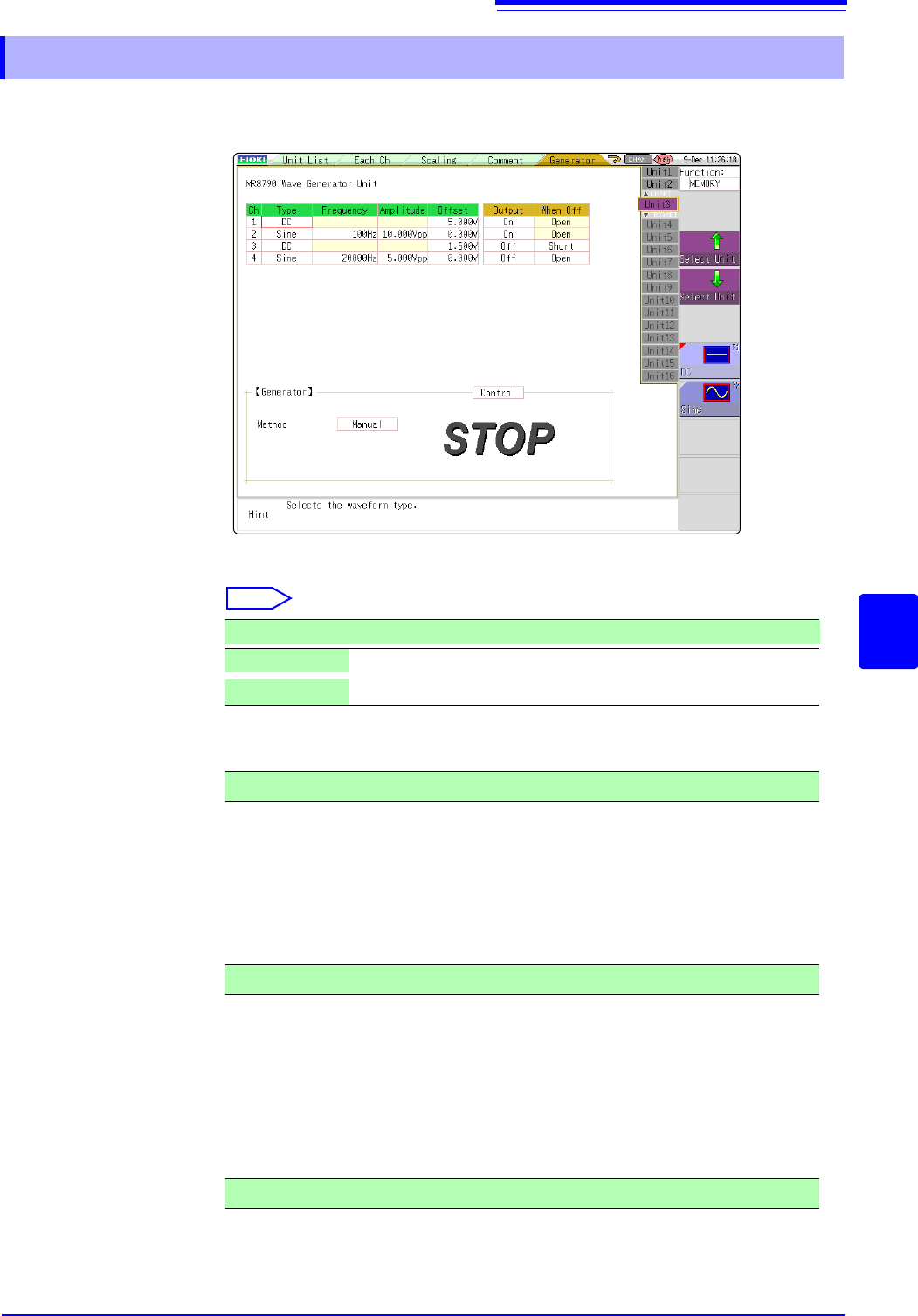
Channels installed with Model MR8790 cannot be measured.
See: "Opening the [Each Ch] sheet, Making a Channel Selection" (p.161)
Type Selects the waveform type.
Select
Frequency Sets the frequency of output signal.
Amplitude Sets the amplitude of output signal.
The output voltage with guaranteed accuracy is the sum of the amplitude and the
offset, between -10 V and +10 V. If the sum of the amplitude and the offset is set
outside the guaranteed accuracy range, parts of the waveform will be clamped to
the upper limit, approximately +14 V and the lower limit, approximately -14 V.
Offset For DC output: Sets DC voltage.
For sine wave output: Sets the offset voltage.
The output voltage with guaranteed accuracy is the sum of the amplitude and the
offset, between -10 V and +10 V. If the sum of the amplitude and the offset is set
outside the guaranteed accuracy range, parts of the waveform will be clamped to
the upper limit, approximately +14 V and the lower limit, approximately -14 V.
7.9.11 Setting Model MR8790 Waveform Generator Unit
Selections Description
DC
DC output (Default setting)
Sine
Sine wave output
0 Hz to 20000 Hz
0.000 V p-p to 20.000 V p-p
-10 V to +10 V

7.9 Setting Details of Modules
178
When Off Sets the output terminal status when the output is OFF.
Select
Output Turns waveform output On/Off.
Select
Control Sets the waveform output.
Select
Method Selects the control method for waveform output.
Select
For details, see the instruction manual of Models U8793, MR8790, and
MR8791.
Selections Description
Open
Opens the output terminals, separating them from internal circuits.
Short
Short-circuits the output terminals, separating them from internal
circuits.
Selections Description
On
Outputs waveform.
Off
Does not output the waveform.
Selections Description
RUN
Starts output.
PAUSE
Pauses output. While output is paused, the output at the time
[PAUSE] was pressed will be output.
STOP
Stops output.
Selections Description
Manual
Restricts control of signal output to Signal Generation screen.
Sync.
Augments manual control with signal output in synchronization with
the start and end of measurement.
START key: Starts output when measurement starts.
STOP key: Stops output when measurement stops
Keys
Augments manual control by allowing signal output to be manipu-
lated using the instrument’s keys.
START key:Starts output.
STOP key: Stops output.
Manual Trigger key: Pauses output.