MR8740、MR8741_user_manual_eng_20191016H.pdf - 第172页
7.8 Copying settings to other channel s (calculation No.) (Copy function) 160 At the following screens, settings can be copied to other ch annels and calculation No. (When the FFT function is used). • Channel settings wi…
7.7 Inverting the Waveform (Invert Function)
159
6
Chapter 7 Utility Functions
7
This applies to the analog channels only. You can invert the plus and minus sides of the waveform.
Example: • When a current sensor is clamped around a wire with its current direction
mark mistakenly in the direction opposite to the current flow
• When a signal is inputted with spring-pulling force negative and spring-com-
pressing force positive; however, you would like to display the results with
spring-pulling force positive and spring-compressing force negative
7.7 Inverting the Waveform (Invert Function)
Procedure
To open the screen: Right-click and select [DISP] Waveform screen Right-click and select [CH.SET]
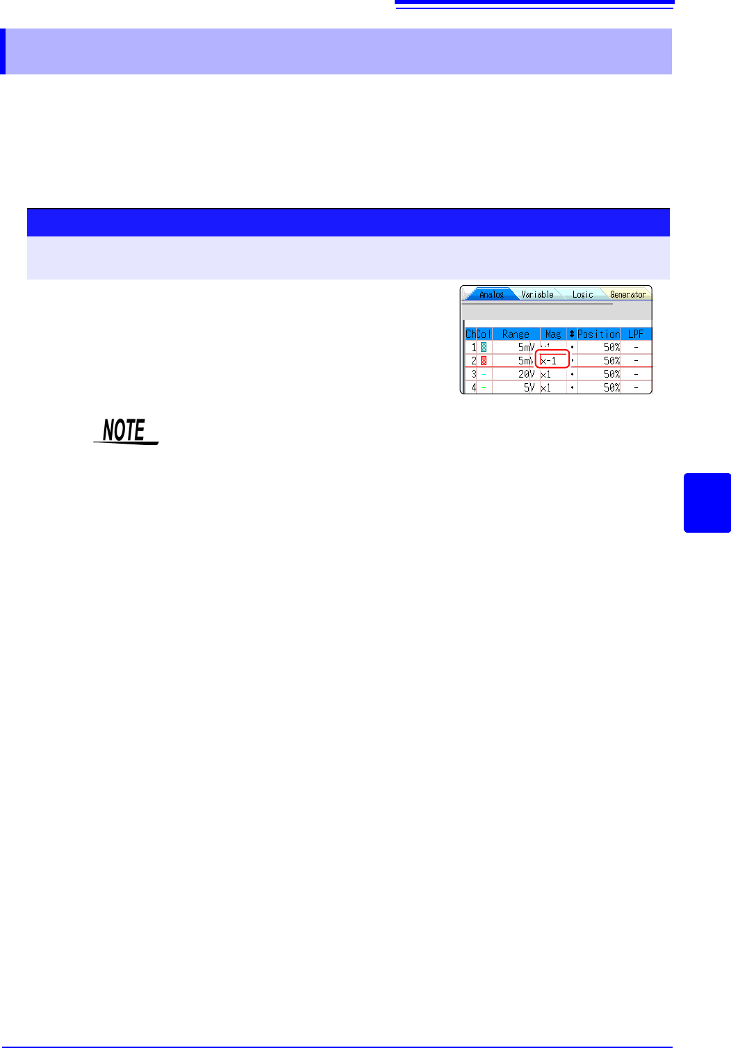
Channel settings window ([Analog] sheet)
1
Move the flashing cursor to the [Mag] item for the channel
whose waveform you want to invert.
2
Select [Invert].
The waveform data (saved file data) is adjusted by the Invert function.
7.8 Copying settings to other channels (calculation No.) (Copy function)
160
At the following screens, settings can be copied to other channels and calculation No. (When the
FFT function is used).
• Channel settings window
• Display range window
• Trigger settings window
• Status screen-[Status] sheet- [Analysis] list and [Scale] list (with FFT func-
tion only)
• Status screen - [Num Calc] sheet
• Status screen-[Wave Calc] sheet
• Channel screen - [Unit List] sheet
• Channel screen - [Scaling] sheet
• Channel screen - [Comment] sheet
The procedure is explained for the Display range window.
7.8 Copying settings to other channels (calcula-
tion No.) (Copy function)
Procedure
To open the screen: Right-click and select [DISP] Waveform screenRight-click and select
[CH.SET]
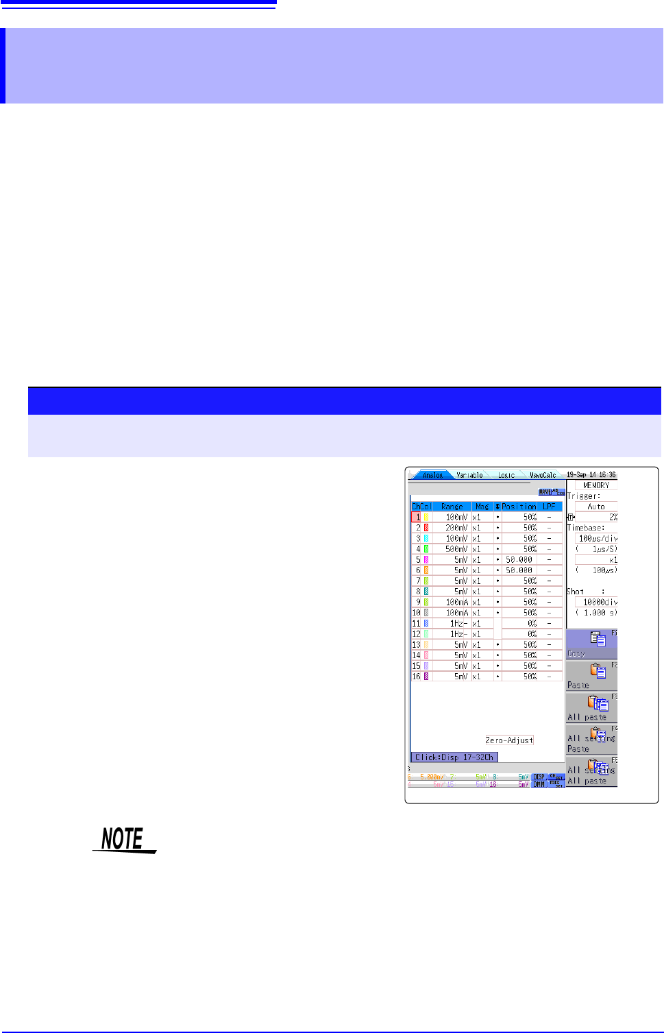
Display range window
1
Click the copy source channel number (calculation
No.).
2
Select [Copy].
3
Click the channel number (calculation No.) where you
want to paste the settings.
4
Select [Paste].
To copy to all channels (calculations), select a chan-
nel number (calculation No.) other than the copy
source and select [All Paste].
When you want to copy all the settings on the Unit list/
Scaling/Variable sheets, select the [All setting
Paste] button or [All setting All paste] button.
When channel settings are copied among different model units, the settings
other than scaling cannot be performed. (Scaling copy is available.)
7.9 Setting Details of Modules
161
6
Chapter 7 Utility Functions
7
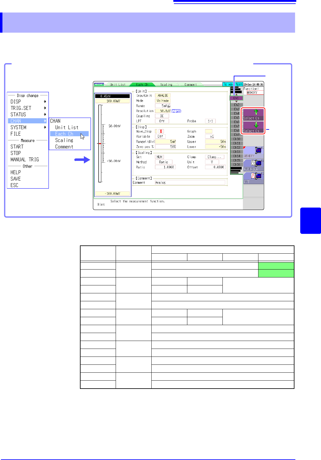
Using the [Each Ch] sheet accessed from the Channel screen, you can make detailed settings.
Logic channel allocation when using Standard LOGIC terminals
*: Ch1 - Ch2 provide 12-bit precision when logic channels LA - LB are used.
When Ch1 to Ch2 are 8970 Freq Unit and standard logic channels LA to LB are
used, the units of corresponding channels can no longer be used.
When the MR8990 Digital Voltmeter Unit is installed on unit 1 (unit 1 or unit 2 in
the case of MR8741), the standard logic can no longer be used.
7.9 Setting Details of Modules
Select
the
channel.
Shows
the chan-
nel num-
ber and
channel
position.
Opening the [Each Ch] sheet, Making a Channel Selection
Click [CHAN] in the right-
click menu.
Module
Memory for each channel (16 bits)
4 bits 4 bits 4 bits 4 bits
Ch1*
Analog
Analog Ch1
LA
Ch2* Analog Ch2
LB
Ch3*
Logic
L2A L2B
-
Ch4* L2C L2D
Ch5
Analog
Analog Ch5
Ch6 Analog Ch6
Ch7
Logic
L4A L4B
-
Ch8 L4C L4D
Ch9
Analog
Analog Ch9
Ch10 Analog Ch10
Ch11
Analog
Analog Ch11
Ch12 Analog Ch12
Ch13
Analog
Analog Ch13
Ch14 Analog Ch14
Ch15
Analog
Analog Ch15
Ch16 Analog Ch16