MR8740、MR8741_user_manual_eng_20191016H.pdf - 第408页
Appendix 3 About Op tions A 12 Application Model Description AC/DC The CT955x or 9318 Conversion Cable are required for connection. Model 9709 AC/DC Current Sensor 500 A, DC to 100 kHz Model CT6841 AC/DC Current Probe 20…

Appendix 3 About Options
A11
Appendix
Module (for generation)
These modules can be installed along with a measurement module.
Application Model
Number of
channels
Maximum output
frequency
Output voltage
Arbitrary waveform generation
U8793 Arbitrary Waveform Generator Unit 2 100 kHz -10 V to 15 V
Sine wave and DC generation
MR8790 Waveform Generator Unit 4 20 kHz ±10 V
Pulse generation
MR8791 Pulse Generator Unit 8 100 kHz 0 to 5 V
Measurement probes, cords, and clamps
Application Model Description
Maximum
input voltage
Mximum rated
voltage to earth
Voltage
measurement
Model L9197 Connection
Cord
For high voltage 600 V AC, DC
600 V AC, DC
(CAT III)
300 V AC, DC
(CAT IV)
Model L9198 Connection
Cord
For low voltage
300 V AC, DC 600 V AC, DC
Model L9790 Conection Cord 600 V AC, DC
600 V AC, DC
(CAT III)
300 V AC, DC
(CAT IV)
Model L9217 Connection
Cord
Isolated BNC-BNC 300 V AC, DC -
Model 9322 Differential Probe
For high voltage
• Model 9418-15 AC Adapter is
required when connecting to the
module for voltage measure-
ment.
2000 V DC,
1000 V AC
(CAT II)
600 VAC, DC
(CAT III)
-
Model P9000-01 Differential
Probe
Model P9000-02 Differential
Probe
The Model Z1008 AC Adapter or a
commercially available USB cable
is required.
1000 VAC, DC
(CAT III)
-
Model 9665 10:1 Probe
Maximum rate voltage above
ground is that of the module.
1 kV rms
(up to 500 kHz)
-
Model 9666 100:1 Probe
Maximum rate voltage above
ground is that of the module.
5 kVpeak
(up to 1 MHz)
-
Model 9166 Connection Cord
For inputting voltage to Model
U8979
30 V AC,
60 V DC
-
Logic signal input
Model 9320-01 Logic Probe
Four channels, for detecting volt-
age and closed/open contact
points
- -
Model MR9321-01 Logic
Probe
Four isolated channels, for detect-
ing AC/DC voltage on/off (for small
terminal types and for lines)
High range
250 V rms
Low range
150 V rms
250 V rms
(CAT II)
Model 9327 Logic Probe
Four channels, for detecting volt-
age and closed/open contact
points (high-speed type)
- -

Appendix 3 About Options
A12
Application Model Description
AC/DC
The CT955x or 9318 Conversion
Cable are required for connection.
Model 9709 AC/DC Current Sensor 500 A, DC to 100 kHz
Model CT6841 AC/DC Current Probe 20 A, DC to 1 MHz
Model CT6843 AC/DC Current Probe 200 A, DC to 500 kHz
Model CT6844 AC/DC Current Probe 500 A, DC to 200 kHz
Model CT6845 AC/DC Current Probe 500 A, DC to 100 kHz
Model CT6846 AC/DC Current Probe 1000 A, DC to 20 kHz
Model CT6862 AC/DC Current Sensor 50 A, DC to 1 MHz
Model CT6863 AC/DC Current Sensor 200 A, DC to 500 kHz
Model CT6865 AC/DC Current Sensor 1000 A, DC to 20 kHz
Dedicated for AC
The CT955x or 9318 Conversion
Cable are required for connection.
Model 9272-10 Clamp On Sensor 20 A/200 A, 1 Hz to 100 kHz
Dedicated for AC
Model 9018-50 Clamp On Probe 10 A to 500 A, 40 Hz to 3 kHz
Model 9132-50 Clamp On Probe 20 A to 1000 A, 40 Hz to 1 kHz
Leakage current
Model 9657-10 Clamp On Leak Sensor 10 A AC (Leakage current, 50 Hz/60 Hz)
Others
For connecting to a module for
voltage measurement
Model CT9555, CT9556, and CT9557
Sensor Unit
For Model 9272-10, 9709, CT6841,
CT6843, CT6844, CT6845, CT6846,
CT6862, CT6863, CT6865
For connecting to the Model
8971 Current Unit
Model 9318 Conversion Cable
For Model 9272-10, 9709, CT6841,
CT6843, CT6844, CT6845, CT6846,
CT6862, CT6863, CT6865
For more information on the output rate of a clamp sensor, see the indication on each clamp sensor or the instruction manual.
Software
Application Software
9333 LAN Communicator
9335 Wave Processor
Appendix 4 FFT Definitions
A13
Appendix
What is FFT? __________________________________________________
FFT is the abbreviation for Fast Fourier Transform, an efficient method to calcu-
late the DFT (Discrete Fourier Transform) from a time-domain waveform. Also,
the reverse process of transforming frequency data obtained by the FFT back
into its original time-domain waveform is called the IFFT (Inverse FFT). The FFT
functions perform various types of analysis using FFT and IFFT.
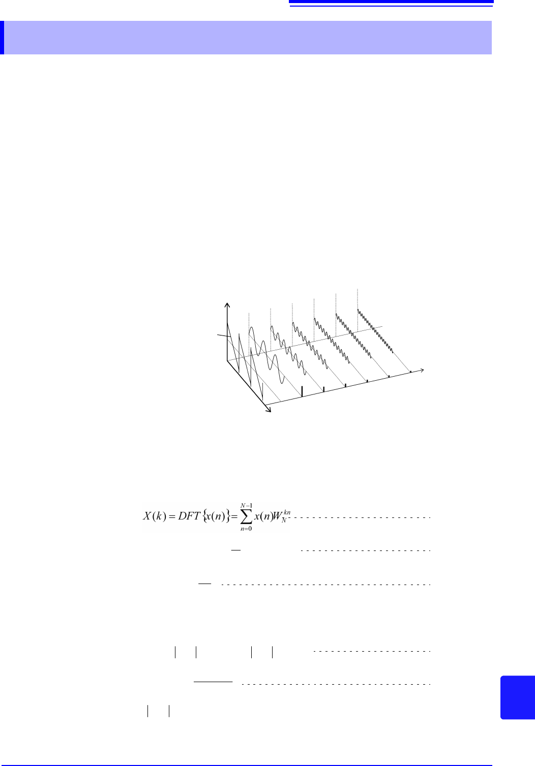
Time and Frequency Domain Considerations _______________________
All signals are input to the instrument as a function of the time domain. This func-
tion can be considered as a combination of sine waves at various frequencies,
such as in the following diagram. The characteristics of a signal that may be diffi-
cult to analyze when viewed only as a waveform in the time domain can be eas-
ier to understand by transforming it into a spectrum (the frequency domain).
Discrete Fourier Transforms and Inverse FFT _______________________
For a discrete signal x(n), the DFT is X(k) and the number of Analysis points is N,
which relate as follows:
X(k) is typically a complex number, so expression (1) can be transformed again
and written as follows:
Appendix 4 FFT Definitions
Amplitude
Frequency
Time
Time-Domain
Waveform
(1)
kn
N
N
n
WkX
N
kXIDFTnx
1
0
)(
1
)()(
N
jW
N
2
exp
(2)
(3)
(4)
(5)
)()()(exp)()( kkFkjkFkF
)(Re
)(Im
tan)(
1
kX
kX
k
: Amplitude spectrum, : Phase spectrum
)(kF
)(k