MR8740、MR8741_user_manual_eng_20191016H.pdf - 第256页
11.2 Display Settings 244 1 1.2 Display Settings Procedure To open th e screen : Right-clic k and select [ST A TUS] [Memory Div] sheet 1 T o display any block on the W aveform screen Set the display blocks Set after me…
11.1 Recording Settings
243
10
Chapter 11 Memory Division Function
11
11.1 Recording Settings
Procedure
To open the screen: Right-click and select [STATUS] [Memory Div] sheet
1
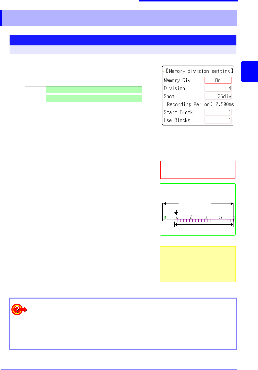
Enable the Memory Division function.
Move the flashing cursor to the
[Memory Div] item.
Select [On].
2
Set the number of divisions.
Move the flashing cursor to the [Division] item.
Set the number of blocks for division.
Default setting: 4
3
Set the recording length.
(This is linked to the recording length setting on the [Status]
sheet.)
Move the flashing cursor to the [Shot] item.
Set the recording length.
The maximum recording length and number of divisions are determined
automatically according to memory capacity and the number of chan-
nels used.
Setting range: "Appendix 2.4 Maximum record length and number of di-
visions (Memory division function)"(p.A7)
4
Set the start block.
Move the flashing cursor to the [Start Block] item.
Set the block number at which to start recording.
Default setting: 1
5
Set the Used Block number.
Move the flashing cursor to the [Use Blocks] item.
Set the number of blocks to use.
Default setting: 1
Off
Memory Division is disabled.(default setting)
On
Memory Division is enabled.
About Recording
When a fast timebase is selected, display-
ing and saving operation are not available
while measuring.
Selecting the display screen for auto sav-
ing lengthens dead time.
Use Blocks (Purple)
Memory Division, Waveform Calcula-
tion, and Roll Mode cannot be enabled
at the same time.
When the number of divisions is 32, the
Start Block is 5 and the Used Block num-
ber (number of blocks to use) is 20
No. of Divisions
Start Block
3
1
2
4
5
To display any block on the waveform screen when finished measuring:
Set the number of blocks to display (p.244).
(This can also be set on the Waveform screen (p.136).)
To display overlaid waveforms:
Set the number of blocks for reference (p.244).
11.2 Display Settings
244
11.2 Display Settings
Procedure
To open the screen: Right-click and select [STATUS] [Memory Div] sheet
1
To display any block on the Waveform screen
Set the display blocks
Set after measurement is complete.(This can also be set on the
Waveform screen (p.136).)
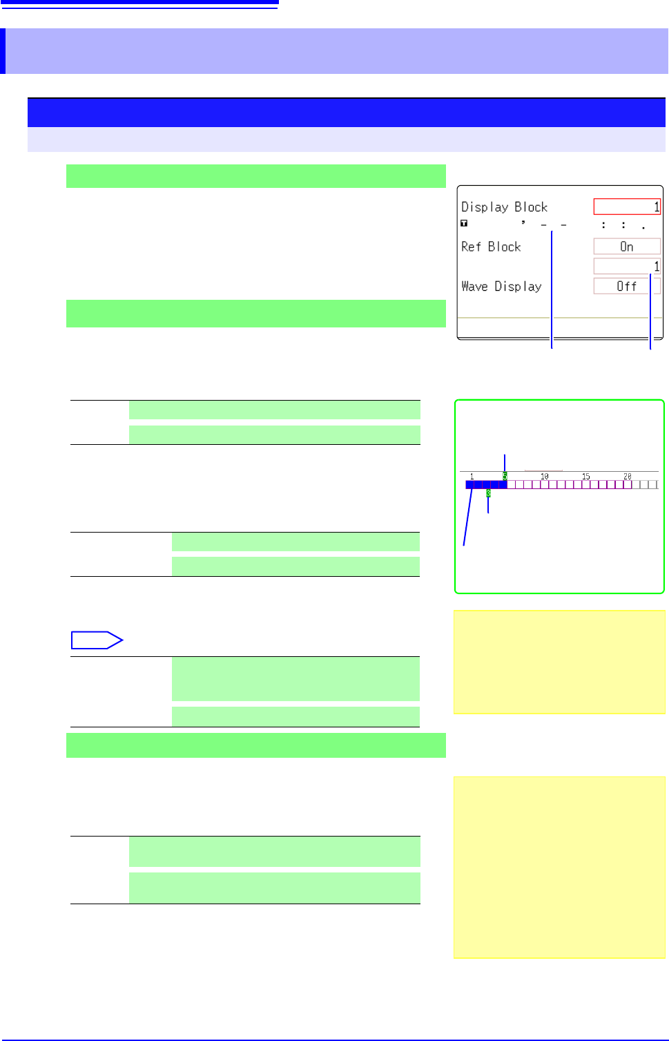
Move the flashing cursor to the [Display Block] item.
Set the number of blocks to display on the Waveform screen.
2
To display multiple blocks as overlaid waveforms
Enable the Reference Block function
Move the flashing cursor to the [Ref Block] item.
Select [On].
3
(When Reference Blocks are enabled [On])
Select whether to reference every block
To overlay all waveforms, select [All Blks On].
To overlay selected waveforms, move the flashing cursor to the num-
ber column of the reference block and select the block number.
Select
4
To display every block as its waveform is acquired
Enable tracking waveform display.
Move the flashing cursor to the [Wave Display] item.
Select [On].
Viewing Memory Division waveforms on the Waveform screen
See: "6.8 Seeing Block Waveforms" (p.136)
Off
Reference Blocks are not displayed (default setting)
On
Reference Blocks overlay Display blocks on the display.
All Blks Off
Set reference to all blocks to Off.
All Blks On
Set reference to all blocks to On.
Ref On-Off
Set On or Off. If [On] is selected, the block frame
of the selected block number is displayed as a
green square.
Select a block.
Off
The waveform of only the last block is displayed after re-
cording up to the number of used blocks. (default setting)
On
Waveforms are displayed one block at a time as they are
acquired at each trigger event.
Display Block (Green)
Reference Block (Light Green)
Measurement data is recorded at the
colored positions.
When the Display Block is 5 and the Ref-
erence Block is 3
Reference Block No.
Enabling the Trace Waveform display
lengthens dead time.
About Dead Time:
See: "Difference Between Dead Times
During Normal and Memory Division
Recording" (p.246)
Even if the Roll Mode is enabled (other
than Off), it is not usable when the Trace
Waveform display is disabled.
Reference Block Selection
Reference Blocks can also be selected
and deselected in the [Ref Block] item on
the [List] display.
See: "Getting Details on Each Block:"
(p.245)
2
4
1
Trigger time
11.2 Display Settings
245
10
Chapter 11 Memory Division Function
11
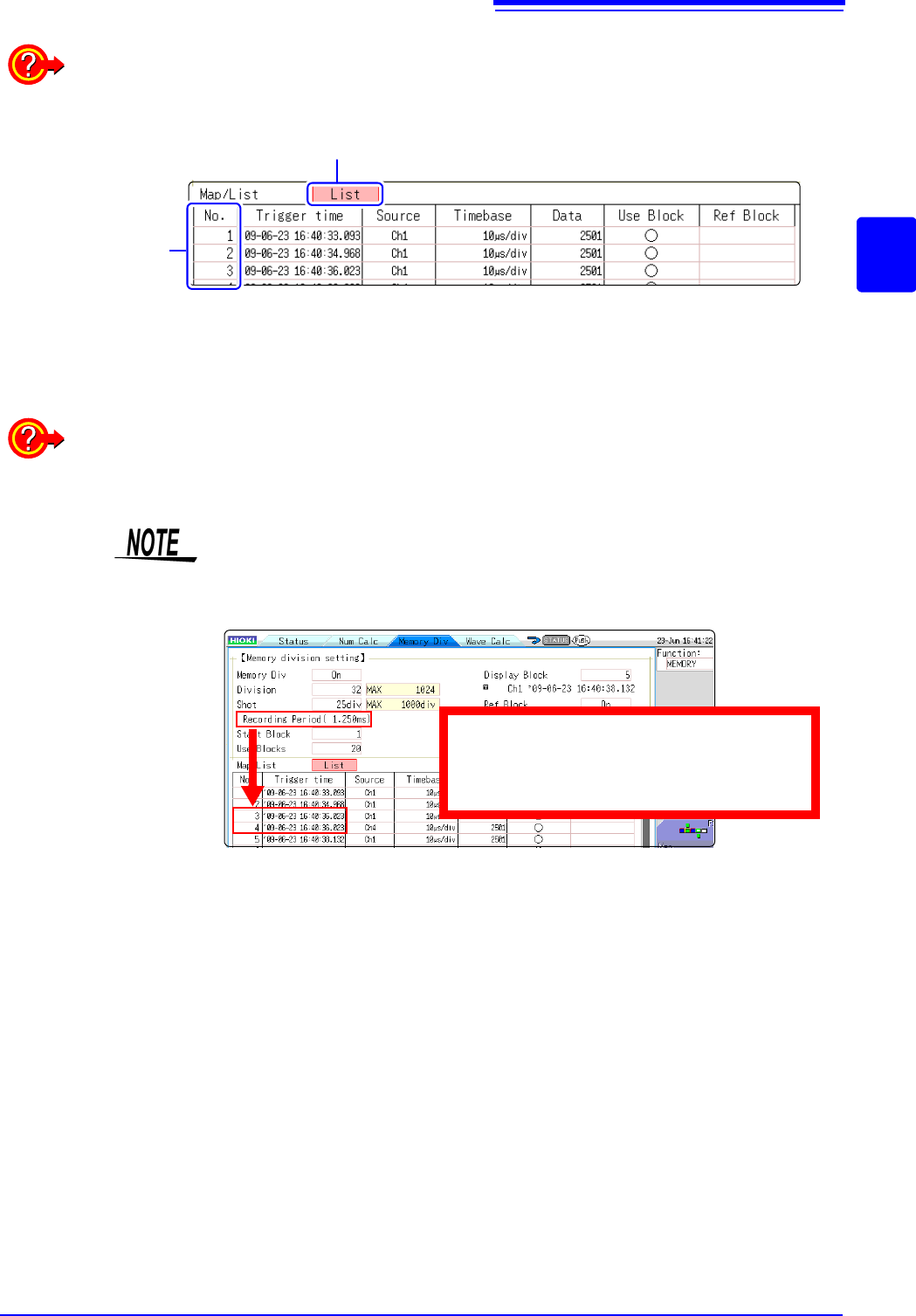
Getting Details on Each Block:
The trigger time and measurement status of each block can be viewed on the list.
Move the flashing cursor to the [Map/List] , and select [List].
Block No.
A block can be selected with the mouse.
You can move the flashing cursor to the Reference Block column to set a block’s on/off state as a
Reference Block.
To switch block waveforms on the Waveform screen:
To be able to select the block you want to see, click [WAVE] in the right-click menu at the Wave-
form screen and switch Pos to Block.
See: "6.8 Seeing Block Waveforms" (p.136)
• When displaying memory division blocks as a list, blocks may have the same
trigger times. This occurs because the minimum resolution of the clock used
by this unit is 1/128th of a second (7.8125 ms) and measurement occurs dur-
ing this interval.
• If triggers occur continuously within an interval shorter than 500 s, the
displayed trigger time may indicate a time slower than reality.
Example:
The recording time is 1.25 ms and the trigger
times of No. 3 and No. 4 blocks may be the
same.