MR8740、MR8741_user_manual_eng_20191016H.pdf - 第59页
2.2 Connecting Cords 47 2 Chapter 2 Measurement Prep arations 1 Align the screw of the miniature con- nector, and turn th e connector cloc k- wise to tighten it. 2 Attach the charge -o utput acceleration sensor to a meas…
2.2 Connecting Cords
46
Acceleration sensor connectable with Model U8979
Measuring acceleration
Connect a acceleration sensor to Model U8979 Charge Unit.
Familiarize yourself with "Handling the Instrument and Modules" ( p.9) before connecting a current sensor.
Applicable Modules
• Model U8979 Charge Unit
The following device can be connected to the module.
• Acceleration sensor (Not available from Hioki)
Use an acceleration sensor with a built-in pre-amplifier that conforms to the
specification of Model U8979 Charge Unit. Using an inapplicable sensor may
cause damaging itself.
Acceleration sensor type Terminal the sensor is connected
to
Note
With a built-in pre-amplifier BNC connector Drive power: 3.5 mA, 22 V
Charge output Miniature connector (#10-32) –
1
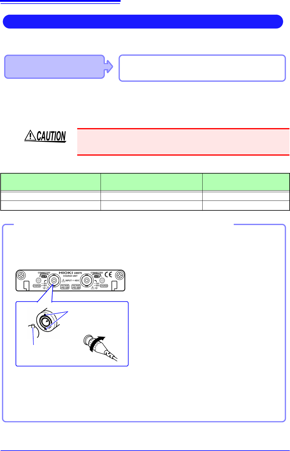
Align the slots in the BNC connector
of anacceleration sensor with the
locking studs of a BNC connector on
the module, and insert the connector.
2
Turn the BNC connector of the accel-
eration sensor clockwise until it locks.
3
Attach the acceleration sensor with
the built-in pre-amplifier to a measure-
ment target.
Connecting a BNC-output acceleration sensor with a built-in pre-amplifier
Connecting an acceleration sensor with a built-in pre-amplifier
Model U8979 Charge Unit
Locking studs of
module side Locking
studs
BNC connector slots
Lock
1
2
Connecting an acceleration sensor other than a sensor with a built-in pre-amplifier
Convert the output connector into the BNC connector using a commercially available conversion con-
nector or conversion cable to connect the sensor.
How to remove the acceleration sensor
Turn the BNC connector of the acceleration
sensor counter-clockwise to release the lock
and remove the connector.
2.2 Connecting Cords
47
2
Chapter 2 Measurement Preparations
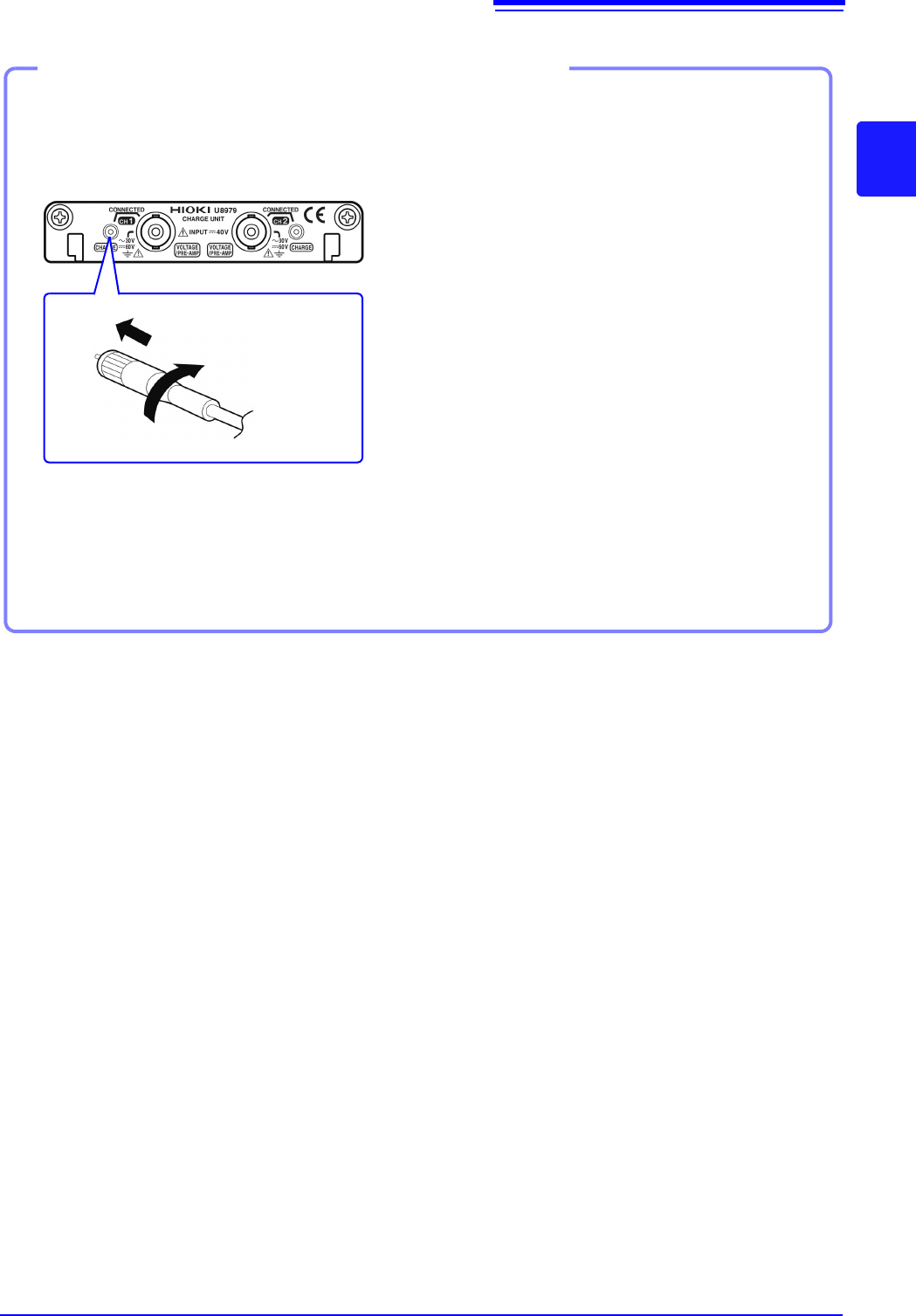
1
Align the screw of the miniature con-
nector, and turn the connector clock-
wise to tighten it.
2
Attach the charge-output acceleration
sensor to a measurement target.
Connecting a charge-output acceleration sensor equipped with the miniature connector
(#10-32)
Connecting a charge-output acceleration sensor
How to disconnect the current sensor
Turn the miniature connector counterclockwise,
and then pull out the connector.
Tighten the screw
Model U8979 Charge Unit
Connecting a charge-output acceleration sensor equipped with a connector other than a
miniature connector (#10-32)
Convert the output connector into the miniature connector (#10-32) using a commercially available
conversion connector or conversion cable to connect the sensor.
2.2 Connecting Cords
48
Use to connect: Logic Probe
• 9320 Logic Probe
*
• 9320-01 Logic Probe
• 9327 Logic Probe
LOGIC terminal
Measuring Logic Signals
Applicable Modules
• Model 8973 Logic Unit
LA to LB (MR8740) and LA to LD
(MR8741) are supplied as standard equip-
ment with the instrument.
Read "Before Connecting a Logic Probe to the Measurement Object" ( p.12) carefully.
For more information about logic probe specifications, see the instruction manual that came with the logic probe you plan to us
Connect to the measurement object
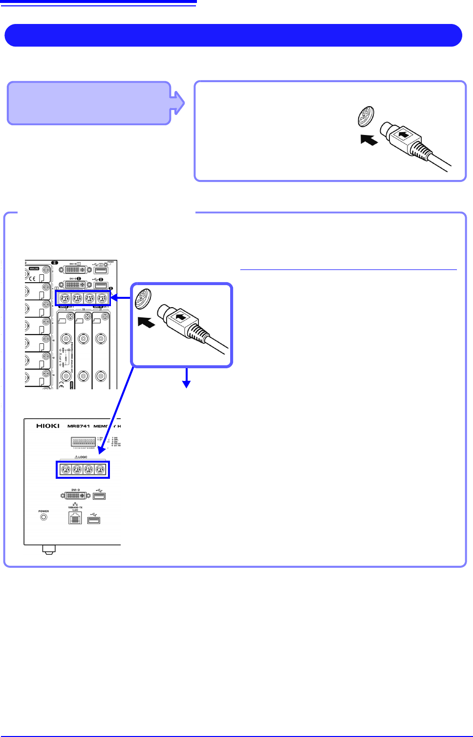
MR8740 Front Side
Example: Connecting the 9327 Logic Probe
1
Connect the logic probe by aligning the
groves on the plug and a LOGIC terminal.
2
Connect to the measurement object.
Required item:Model 9327 Logic Probe
LOGIC terminals
2
1
Connect to LOGIC Terminals
MR8741 Front Side