MR8740、MR8741_user_manual_eng_20191016H.pdf - 第364页
17.6 Specifications of Modules 352 17.6 Sp ecifications of Modules 17.6.1 8966 Analog Unit Temperature and hu midity range for guaranteed accuracy 23°C ± 5°C (73.4°F ± 9.0°F), 20 to 80% RH (when zero adjustment is ex ecu…

17.5 Built-In Functions
351
Chapter 17 Specifications
16
17
Others
*1:When an LCD monitor is connected or when displaying the Waveform screen via a computer using
the HTTP function
*2: Model MR741 only
On-line help function*
1
Clicking [HELP] displays help for the item at the currently selected (blinking) item (the whole
screen is not used)
Basic help (when making settings, displays a brief description of the selected (blinking) item along
the bottom of the screen)
Grid types*
1
Display only: Off, normal or normal (dark)
Comment display*
1
Comments are displayed with channel numbers on the screen (channel markers)
Time scale display*
1
Time, time (base-60), scale, date, sample numbers
Variable auto-compensation*
1
OFF, ON
Start backup function OFF, ON
Display color*
1
Color 1 to 3, or user-defined
Beep sound Off, warnings, or warnings and operations
Language*
1
Japanese/ English/ Korean/ Chinese
Start action Click once, or twice
Stop action Click once, or twice
GUI section saving Off / On
External control erminals*
2
Trigger control terminals (EXT.TRIG, TRIG OUT),
External sampling input terminal (EXT.SMPL)
Remote control input terminal (START/IN1, STOP/IN2, SAVE/IN3),
Evaluation output terminals (GO/OUT1, NG/OUT2)
Remote control*
2
Select from among terminals for remote input (START/IN1, STOP/IN2, SAVE/IN3):
[START] [STOP] [START/STOP] [ABORT] [PRINT] [SAVE] [Pen Up/Down] [RUN/STOP] [PAUSE]
Internal status output*
2
Select from among evaluation output terminals (GO/OUT1, NG/OUT2): [Error], [BUSY], [Trigger]
Probe calibrationoutput*
2
Select evaluation output terminal (NG/OUT2): [Probe Calibration]
Evaluation output*
2
Select from among evaluation output terminals (GO/OUT1, NG/OUT2):
[Measure], [Waveform Evaluation], [Value Evaluation or Waveform Evaluation],
[Value Evaluation and Waveform Evaluation]
Time setting Included (settable with mouse or communication command)
Initialization Clear waveform data
System reset (Settings/System settings 1 [Environment]/System settings 2 [Interface])
Self-Test function ROM/RAM, Display, System information, USB host

17.6 Specifications of Modules
352
17.6 Specifications of Modules
17.6.1 8966 Analog Unit
Temperature and humidity
range for guaranteed accuracy
23°C ± 5°C (73.4°F ± 9.0°F), 20 to 80% RH (when zero adjustment is executed 30 minutes after
power on)
Product warranty period 3 years
Period of guaranteed accuracy 1 year
No. of input channels 2 channels
Measurement range 5, 10, 20, 50, 100, 200, 500 mV, 1, 2, 5, 10, 20 V/div
Measurement accuracy ± 0.5% f.s.(Filter 5 Hz On)
Temperature characteristic ± 0.06% f.s./°C
Frequency characteristic DC Coupling: DC to 5 MHz -3 dB
AC Coupling: 7 Hz to 5 MHz -3 dB (low cut-off frequency 7 Hz ± 50%)
Noise 1.5 mVp-p (typ), 2 mVp-p (max) (sensitivity range, with input shorted)
Common mode rejection ratio 80 dB minimum (at 50/60 Hz and with signal source resistance 100 maximum)
Low-pass filter OFF, 5 ± 50%, 50 ± 50%, 500 ± 50%, 5k ± 50%, 50 k ± 50%, 500 k ± 50%(Hz)-3dB
Input type Unbalanced (floating)
Input coupling AC/ DC/ GND
Input resistance 1 M ± 1%
Input capacitance 30 pF ± 10 pF (at 100 kHz)
A/D resolution 12 bit
Maximum sampling rate 20 MS/s
Input terminals Insulated BNC terminal
Maximum input voltage 400 VDC
Maximum rated voltage to
earth
300 V AC, DC (between input channels and chassis, and between input channels),
Measurement category II (anticipated transient overvoltage 2500 V)
Operating temperature and
humidity
Same as the host Memory HiCorder
Operating environment Same as the host Memory HiCorder
Storage temperature and hu-
midity
Temperature -10 to 50°C (14 to 122°F) Humidity 80% RH or less (non-condensating)
Dimensions Approx. 106 mmW × 19.8 mmH × 207.5 mmD (4.17"W × 0.78"H × 8.17"D)
Mass Approx. 250 g (8.8 oz)
Effect of radiated radio-fre-
quency electromagnetic field
± 15% f.s. (max) at 3 V/m
Effect of conducted radio- fre-
quency electromagnetic field
±45% f.s. (max) at 3 V (100 mV/div range, with 1 VDC input)
Applicable standards Safety EN61010
EMC EN61326 Class A
17.6 Specifications of Modules
353
Chapter 17 Specifications
16
17
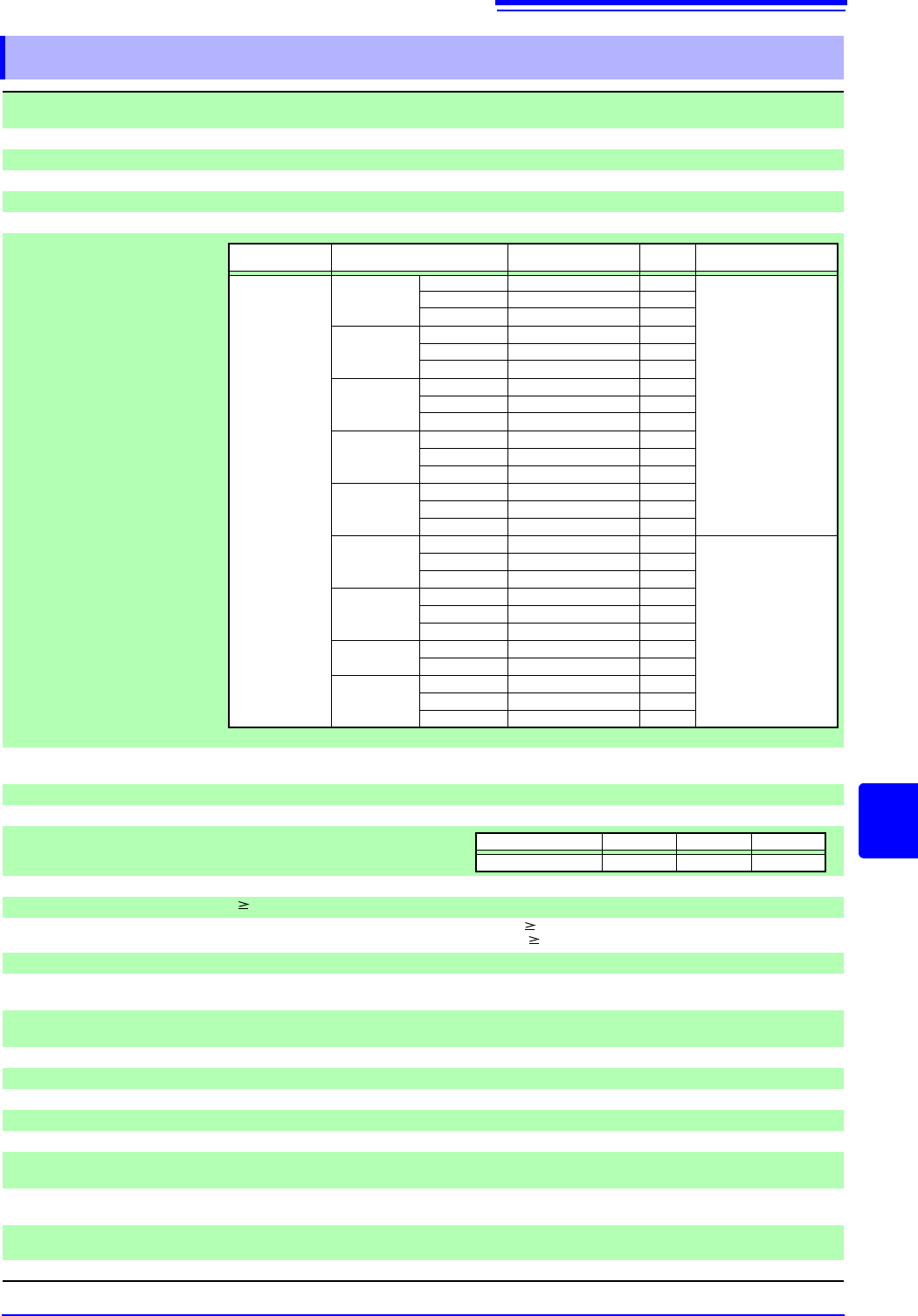
17.6.2 8967 TEMP Unit
Temperature and humidity
range for guaranteed accuracy
23°C ± 5°C (73.4°F ± 9.0°F), 20 to 80% RH (when zero adjustment is executed 30 minutes after
power on)
Product warranty period 3 years
Period of guaranteed accuracy 1 year
No. of input channels 2 channels
Input terminals Pushbutton-type terminal block (2 terminals/ch)
Sensor Thermocouple (K, J, E, T, N, R, S, B, W)
Measurement ranges
Measurable range
Resolution
Measurement accuracy
(f.s.=20 div)
Reference junction compensa-
tion accuracy
± 1.5°C (Reference junction compensation: When internal, add to thermocouple measurement ac-
curacy)
Reference junction compensation
Selectable internal or external (during thermocouple measurement)
Temperature characteristic Add (meas. accuracy × 0.1)°C to meas. accuracy
Data refresh Selectable from normal, fast or slow
Open-circuit detection Selectable On or Off
Input resistance 100M (with open-circuit detection Off) or 5.1 M± 5% with open-circuit detection On)
Common mode rejection ratio 80 dB minimum (at 50/60 Hz, with signal source 100, and Fast data refresh setting)
100 dB minimum (at 50/60Hz, with signal source 100, and Normal data refresh setting)
Input type Unbalanced (floating)
Maximum rated voltage to
earth
300 V AC, DC (between input channels and chassis, and between input channels)
Measurement category II, (anticipated transient overvoltage 2500 V)
Operating temperature and
humidity
Same as the host Memory HiCorder
Storage temperature and humidity
Temperature-20 to 50°C (-4 to 122°F), Humidity 90% RH or less (non-condensating)
Operating environment Same as the host Memory HiCorder
Dimensions Approx. 106 mmW × 19.8 mmH × 204.5mmD (4.17"W × 0.78"H × 8.05"D)
Mass Approx. 240 g (8.8 oz)
Option Ferrite clamp-on choke........................................................................................2
Effect of radiated radio-fre-
quency electromagnetic field
± 2% f.s. (max) at 3 V/m
Effect of conducted radio- fre-
quency electromagnetic field
± 2% f.s. (max) at 3 V
Applicable standards Safety EN61010
EMC EN61326 Class A
Options (sold separately) Model 9810 Thermocouples (K)
Sensor Range Measurable range
Resolu-
tion
Measurement accuracy
Thermocouple
(not including
standard junction
compensation
accuracy)
K
*1
10°C/div -100°C to 200°C 0.01°C
±0.1% f.s. ± 1°C
± 0.1% f.s. ± 2°C
(-200°C to 0°C)
50°C/div -200°C to 1000°C 0.05°C
100°C/div -200°C to 1350°C 0.1°C
J
*1
10°C/div -100°C to 200°C 0.01°C
50°C/div -200°C to 1000°C 0.05°C
100°C/div -200°C to 1100°C 0.1°C
E
*1
10°C/div -100°C to 200°C 0.01°C
50°C/div -200°C to 800°C 0.05°C
100°C/div -200°C to 800°C 0.1°C
T
*1
10°C/div -100°C to 200°C 0.01°C
50°C/div -200°C to 400°C 0.05°C
100°C/div -200°C to 400°C 0.1°C
N
*1
10°C/div -100°C to 200°C 0.01°C
50°C/div -200°C to 1000°C 0.05°C
100°C/div -200°C to 1300°C 0.1°C
R
*1
10°C/div 0°C to 200°C 0.01°C
± 0.1% f.s. ± 3.5°C (0°C to
400°C)
(except B, for which accu-
racy is not guaranteed be-
low 400°C)
± 0.1% f.s. ± 3°C (400°C
and higher)
50°C/div 0°C to 1000°C 0.05°C
100°C/div 0°C to 1700°C 0.1°C
S
*1
10°C/div 0°C to 200°C 0.01°C
50°C/div 0°C to 1000°C 0.05°C
100°C/div 0°C to 1700°C 0.1°C
B
*1
50°C/div 400°C to 1000°C 0.05°C
100°C/div 400°C to 1800°C 0.1°C
W
*2
(WRe5-26)
10°C/div 0°C to 200°C 0.01°C
50°C/div 0°C to 1000°C 0.05°C
100°C/div 0°C to 2000°C 0.1°C
*1: JIS C 1602-1995, *2: ASTM E-988-96
Selection Fast Normal Slow
Data Refresh Rate 1.2 ms 100 ms 500 ms