MR8740、MR8741_user_manual_eng_20191016H.pdf - 第33页
1.4 Screen Configuration 21 1 Chapter 1 Overview Element s common to the S t atus scre en, Channel screen, System screen, and File screen Sheet t abs Shows the names of sheets that can be selected. Click a tab to switch …
1.4 Screen Configuration
20
Explanation of Screen Contents __________________________________
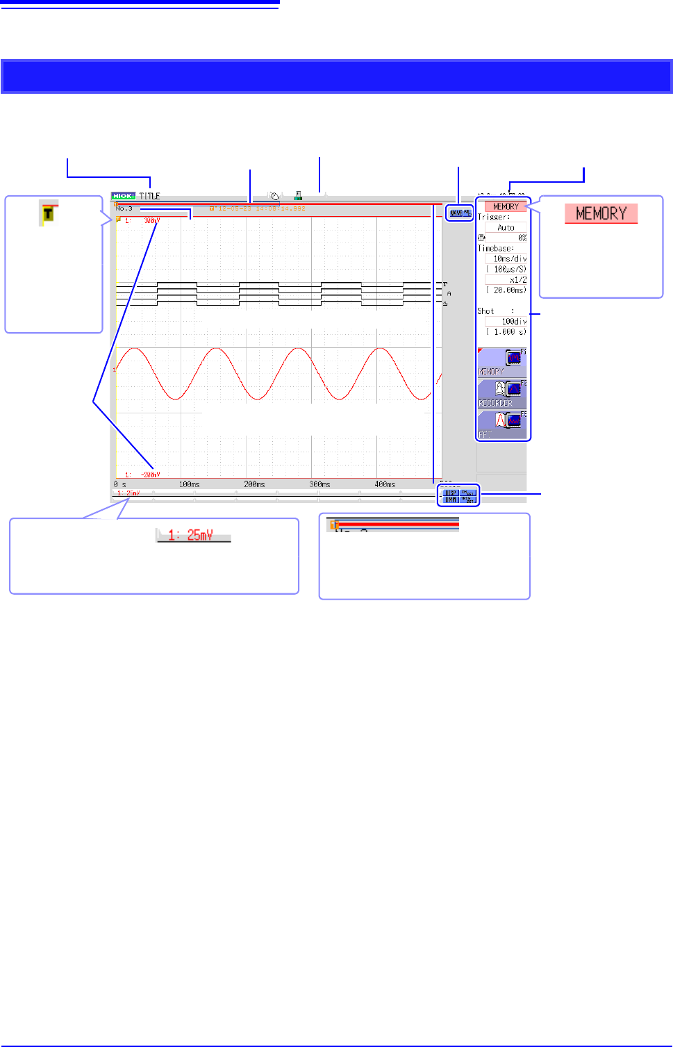
Waveform Screen
Logic waveform (p.79)
Analog waveform (p.76)
Storage counter
Shows how many trigger events occurred. (p.82)
Current date
and time
Shows the set date
and time. (p.57)
Settings cursor
The current cursor lo-
cation is indicated by
flashing.
Title comment
Shows the set title com-
ment. (p.138)
Trigger
marker
Shows the point
where the trigger
event occurred.
(p.189)
Settings window
Set the measurement pa-
rameters here. (p.65)
Trigger time
Shows the date and
time of the last trig-
ger event. (p.189)
Vertical axis display
Shows the value per increment for each channel. This is
linked to the vertical axis (voltage axis) range setting.
(p.76)
Upper and
lower limits
The upper and lower
limit values for each
channel are shown
here. (p.134)
Scroll bar
The stored waveform is indicated by a
red bar, and the displayed waveform by a
blue frame. (p.125)
Media icon
Shows the media status.
(p.53)
Operation icons
Left-click to scroll the wave-
form or operate the A/B cur-
sors.
Display and setting
icons
Left-click to display the
waveforms and numerical
values or make channel
settings.
1.4 Screen Configuration
21
1
Chapter 1 Overview
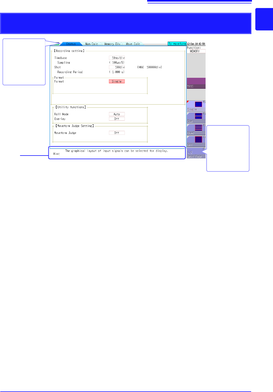
Elements common to the Status screen, Channel screen, System screen, and
File screen
Sheet tabs
Shows the names of
sheets that can be
selected.
Click a tab to switch
to the corresponding
sheet.
Hint
Shows an explanation about the item where the settings cursor is currently located.
Messages such as "Online" and error messages are also shown here.
Next Page
This is shown if there
are more than six se-
lection items.
Selecting this button
displays the other
items.
1.5 Basic Operations
22
You can use a mouse to make various settings on the instrument. This section explains how to per-
form mouse operations.
Use a commercially available USB mouse to operate the instrument.
The following describes how to operate the instrument with a mouse:
1.5 Basic Operations
1.5.1 Mouse Operations
• There are a variety of mice available, and not all mice will work with the instru-
ment.
• The instrument's USB ports are designed exclusively for use with mice and
USB memory sticks. Do not connect any other type of device.
• With some USB devices, the instrument may not start up if the power is turned
on while the USB device is connected to a USB connector. If that happens,
connect the USB device after turning on the power.
• When the instrument is operated with a mouse, some screens may not display
properly.
• External interference may cause the mouse to malfunction. Keep the mouse
and mouse cable as far away as possible from sources of interference.
• Do not use a USB hub because mouse operation may not be possible. Also,
do not connect two mice.
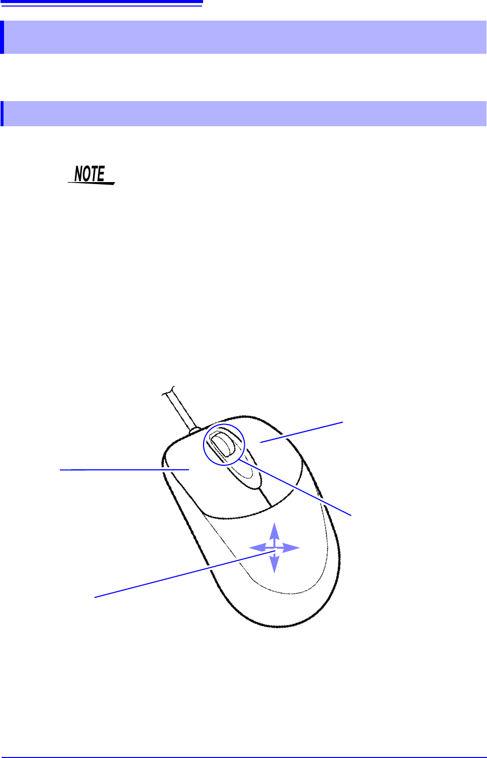
Right-click
Displays a menu with a list of screens.
Grayed-out screens cannot be dis-
played.
Center wheel
Changes the selected item.
On the File screen, you can use the
center wheel to change the selected
file. When measuring with memory
division, you can use the center
wheel to change the displayed
block.
On the Waveform screen, you can
use the center wheel to scroll the
waveform or move the A/B cursors.
Left-click
Left-click to select menus and to select items
on menus. When measuring with memory di-
vision, you can change the displayed block by
double-clicking.
Click the current path shown on the File
screen to move one level up in the folder hier-
archy.
Up/down/left/right
Moves the mouse cursor up, down, left, and
right on the screen.
Convenient features: Shortcut operations
Drag the mouse in any of the following directions while the right mouse button is held down to perform the corre-
sponding shortcut operation.
Drag right: START operation
Drag left: STOP operation
Drag up: ESC operation