MR8740、MR8741_user_manual_eng_20191016H.pdf - 第85页
3.5 Input Channel Setting 73 3 Chapter 3 Measuremen t Procedure Set the analog channel and logic chann el. 3.5 Input Channel Setting See: "Displayin g All Channels for Making the V ariable Function Setting" (p.…
3.4 Setting Measurement Configuration
72
You can specify the format in which the input signal is shown on the Waveform screen.
With 2, 4, 8, or 16 screens, analog channels can be freely assigned to the respective graphs.
3.4.4 Screen Layout
Selecting X-Y1 screen or X-Y4 screen allows waveform X-Y synthesis.
(This applies to the Memory function.)
See: "6.4 Performing Waveform X-Y Synthesis" (p.127)
Procedure
To open the screen: Right-click and select [STATUS] [Status] sheet
Memory Function case
Move the flashing cursor to the [Format] item.
Select
Single Display and record using 1 graph. (default setting)
Dual
Display and record using 2 graphs.
Quad
Display and record using 4 graphs.
Oct
Display and record using 8 graphs.
Hex Display and record using 16 graphs.
XYSingle
Set input signal to X-Y and display and record the correlation using 1 graph.
XYQuad
Set input signal to X-Y and display and record the correlation using 4 graphs.
Analog Channel Assignment
Procedure
To open the screen: Right-click and select [CHAN] [Unit List] sheet
1
Move the flashing cursor to the [Graph] item.
2
Select the display screen for each channel.
The sequence is Gr1, Gr2, Gr3... from the top.
Gr1
Gr2
Gr3
Gr4
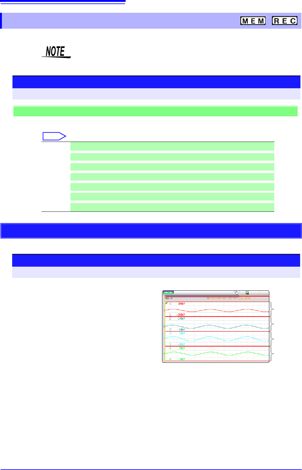
<Sample screen after setting>
3.5 Input Channel Setting
73
3
Chapter 3 Measurement Procedure
Set the analog channel and logic channel.
3.5 Input Channel Setting
See: "Displaying All Channels for Making the Variable Function Setting" (p.157)
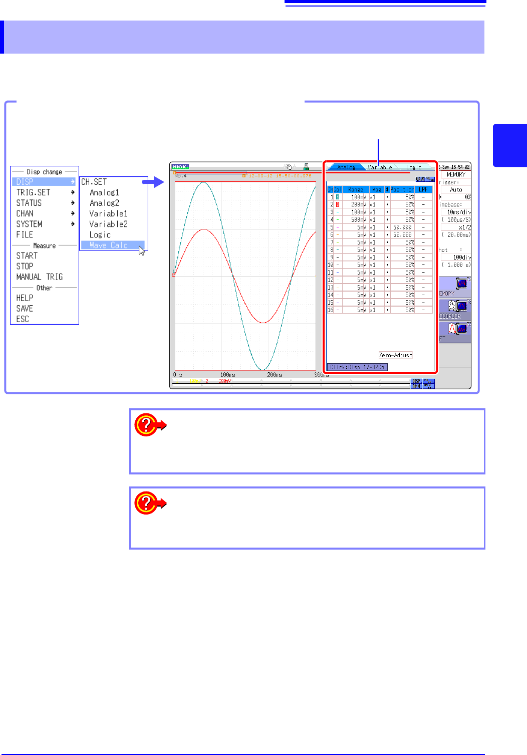
Opening the Channel settings window
You can switch setting
screens by clicking a tab.
Click [DISP]→ [CH.SET] in the
right-click menu.
To hide waveform interpolation
Set the waveform display color in the channel setting window to Off.
See: "1. Waveform Display Color" (p.76)
To copy the settings of one channel to another
See: "7.8 Copying settings to other channels (calculation No.) (Copy func-
tion)" (p.160)
3.5 Input Channel Setting
74
Explains the workflow to make settings for the analog channels (MR8740: Ch1 - Ch32, MR8741:Ch1 -
Ch16).
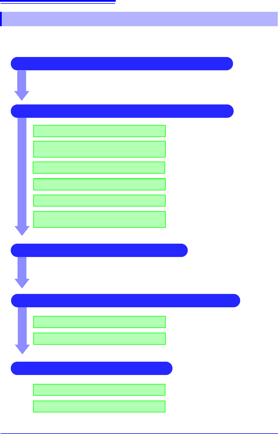
3.5.1 Channel Setting Workflow
2 Make input and screen display related settings
Make filter settings (if noise occurs)
Select input coupling
Match range to measurement target input value
(as necessary)
See:
"3. Coupling" (p.76)
"2. Vertical axis (Voltage axis) Range" (p.76)
"7.4 Converting Input Values (Scaling Func-
tion)" (p.148)
"7. Low-pass filtering" (p.78)
3 Make trigger settings (as necessary)
4 Make display color and display position settings
See:
"Chapter 8 Trigger Settings" (p.189)
1 Select the channels to use (Memory function) only)
Convert input value (as necessary)
Fine-tune waveform amplitude (as necessary)
Set zoom on vertical axis (voltage axis) direction
(as necessary)
"5. Vernier" (p.77)
"4. Vertical axis (Voltage axis) Zoom" (p.77)
Set waveform display color
Set display position and scaling (as necessary)
See:
"1. Waveform Display Color" (p.76)
"7.5 Variable Function (Setting the Waveform
Display Freely)" (p.155)
4 Make graph display settings
For 1, 2, 4, 8, 16 screens
For X-Y1, X-Y4 screens
See:
"Analog Channel Assignment" (p.72)
Procedures "4" and “5” of "6.4 Performing
Waveform X-Y Synthesis" (p.128)