MR8740、MR8741_user_manual_eng_20191016H.pdf - 第354页
16.2 External I/O (MR8741 Only) 342 You can input external sign als as trigger source s. In addition, multiple MR8741s can be u sed for parallel synchronous operation. 1. Connect the cables for the co rresponding externa…
16.2 External I/O (MR8741 Only)
341
13
Chapter 16 External Control (MR8741 Only)
15
16
You can output a signal when a trigger event occurs. In addition, multiple MR8741s can be used for
parallel synchronous operation.
1. Connect the cables for the output signals to TRIGOUT and GND terminals.
See: "16.1 Connecting External Control Terminals (MR8741 Only)" (p.336)
2. On the SYSTEM screen, open the [Environment] sheet and move the cursor to
the [TRIG.OUT] item.
3. Select the output signal type for the trigger output terminal.
Select
4. When trigger event occurs, a pulse wave changing from the HIGH level (4.0 to
5.0 V) to the LOW level (0 to 0.5 V) is output from the TRIG OUT terminal.
*
: Triggering should occur when the signal voltage level changes from HIGH to LOW.
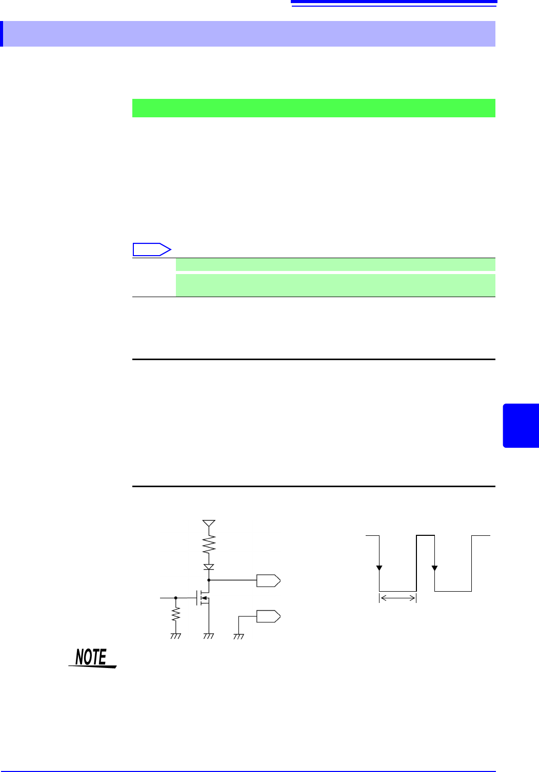
16.2.4 Trigger Output (TRIG OUT)
Signal Output Procedure
Pulse After LOW level output, the signal goes HIGH after a specified interval.
Level
After the trigger is established, a LOW level signal will be outputted during the waveform
retrieval.
Output signal Open drain output (with voltage output), active LOW
*
Output voltage
range
HIGH level: 4.0 to 5.0 V, LOW level: 0 to 0.5 V
(current value:15 mA)
Pulse width Pulse width at pulse setting time : 2 ms ± 1 ms
Pulse width at level setting time: (sampling rate × no. of data
points after trigger) or more
Maximum input
voltage
50 VDC, 50 mA, 200 mW
HIGH
4.0 to 5.0 V
LOW
0 to 0.5 V
GND
TRIG OUT
10 k
10 k
5 V
1 ms or
greater
When using memory division, the trigger output (TRIG_OUT terminal output)
may output the Low level or output erratically in the following conditions.
• The time axis range is 5 s/div to 100 s/div
• The record (measurement) time is 5 ms or less
• Tracking wave display is [OFF].
16.2 External I/O (MR8741 Only)
342
You can input external signals as trigger sources. In addition, multiple MR8741s can be used for
parallel synchronous operation.
1. Connect the cables for the corresponding external input signals to the EXT.TRIG
and GND terminals.
See: "16.1 Connecting External Control Terminals (MR8741 Only)" (p.336)
2. In the Trigger Settings window, set External trigger to [On].
3. On the SYSTEM screen, open the [Environment] sheet and move the cursor to
the [EXT.TRIG] item.
4. Select whether the trigger event occurs on the rising edge () of the waveform or
the falling edge (
).
5. Short-circuit the EXT.TRIG terminal and GND, or input a HIGH level (3.0 to 5.0
V) or LOW level (0 to 0.8 V) pulse wave or rectangular wave to the EXT.TRIG
terminal.
A trigger event occurs on the rising or falling edge of the input waveform.
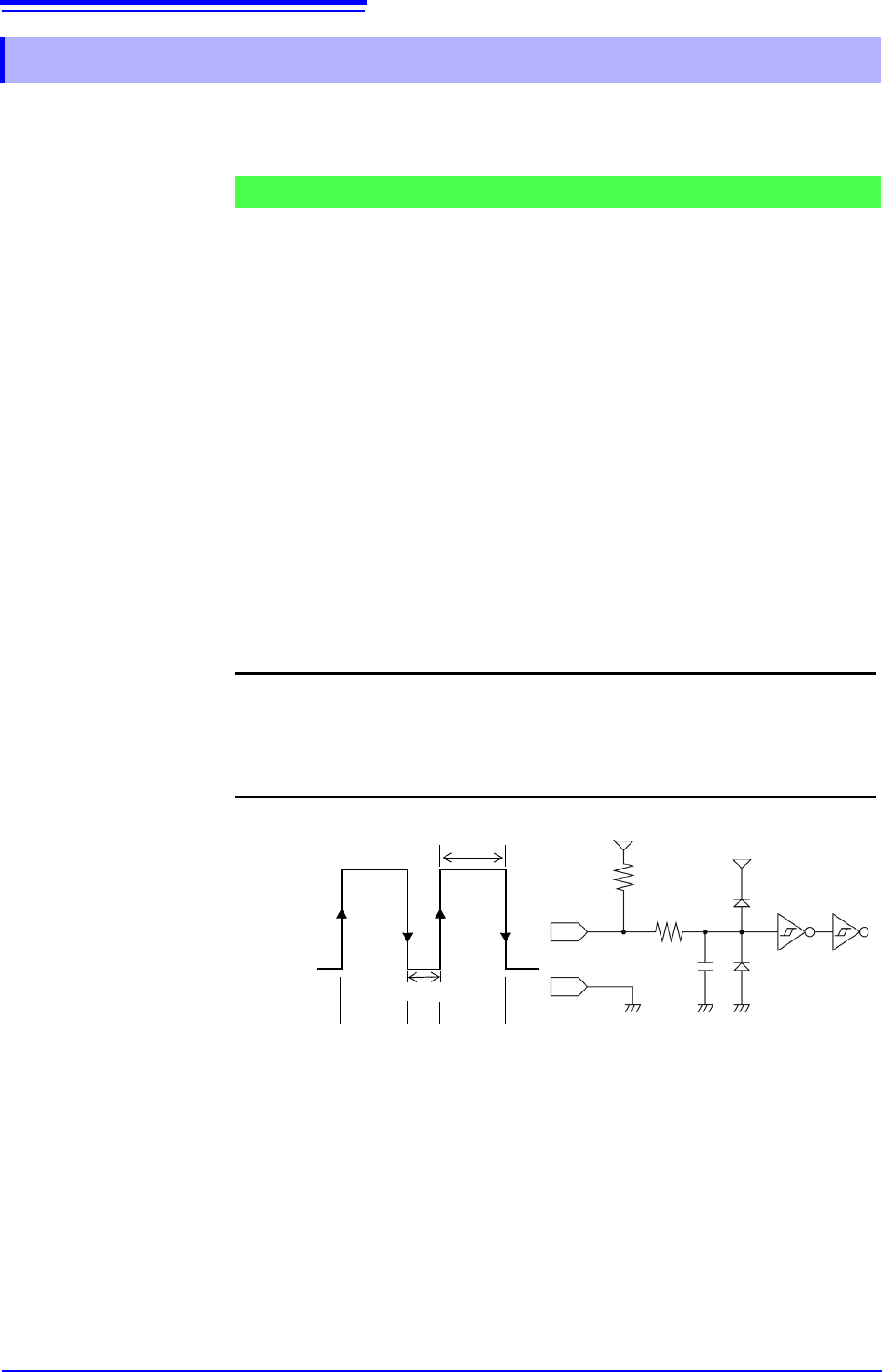
16.2.5 External Trigger terminal (EXT.TRIG)
Signal Input Procedure
Output signal HIGH level: 3.0 to 5.0 V, LOW level: 0 to 0.8 V
Pulse width HIGH level: 50 ns or greater, LOW level: 50 ns or greater
Maximum input
voltage
-0.5 to 7 V
HIGH
3.0 to 5.0 V
LOW
0 to 0.8 V
50 ns or greater
50 ns or greater
GND
150 pF
100
3.3 k
5 V
EXT.TRIG
[ ] [ ]
[ ]: Rising setting [ ]: Falling setting
[ ][ ]
5 V

17.1 General Specifications of the Instrument
343
Chapter 17 Specifications
16
17
Basic Specifications
Specifications Chapter 17
17.1 General Specifications of the Instrument
Measurement functions • Memory Function (high-speed data saving)
• Recorder Function (real time recording)
• FFT Function (frequency analysis)
Maximum number of channels MR8740: Block I 32 analog channels + 8 logic channels, or
26 analog channels + 56 logic channels at a maximum (Together with the
logic channels the instrument provides, when 3 modules of Model 8973
Logic Unit are installed)
Block II 22 analog channels + 8 logic channels, or
16 analog channels + 56 logic channels at a maximum (Together with the
logic channels the instrument provides, when 3 modules of Model 8973
Logic Unit are installed)
MR8741: 16 analog channels + 16 logic channels, or
10 analog channels + 64 logic channels at a maximum (Together with the
logic channels the instrument provides, when 3 modules of Model 8973
Logic Unit are installed)
Number of modules MR8740: Block I Up to 16 modules
Block II Up to 11 modules
Restrictions
• Up to 4 modules of Model 8971 Current Unit can be installed.
• Block I: Up to 3 modules of Model 8973 Logic Unit can be installed in ev-
ery slot except those for Unit 9 through Unit 16.
Block II: Up to 3 modules of Model 8973 Logic Unit can be installed in
every slot except those for Unit 9 through Unit 11.
MR8741: Up to 8 modules
Restrictions
• Model 8971 Current Unit cannot be used.
• Up to 3 modules of Model 8973 Logic Unit can be installed.
Number of the instrument
logic channels
MR8740: Block I 8 (The input connectors of logic probes share the ground with the instru-
ment.)
Block II 8 (The input connectors of logic probes share the ground with the instru-
ment.)
Restrictions imposed when the instrument logic channels are used (com-
mon to block I and II)
• Measurement resolution of each measuring module decreases to 12 bits
when the module is installed in a slot for Unit 1 or Unit 2.
• No frequency measuring modules are available when the module is in-
stalled in the slots for Unit 1 or Unit 2.
• Installing Model MR8990 Digital Voltmeter Unit in both slots for Unit 1
and Unit 2 disables the instrument logic channels.
MR8741: 16 (The input connectors of logic probes share the ground with the instrument.)
• Installing Model MR8990 Digital Voltmeter Unit in both slots for Unit 1 and Unit 2 dis-
ables the instrument logic channels.
• Restrictions imposed when the logic instrument channels are used (when the logic
measurement is set to on)
Measurement resolution of each measuring module decreases to 12 bits when the
module is installed in a slot for Unit 1 or Unit 2.
No frequency measuring modules are available when the module is installed in the
slots for Unit 1 or Unit 2.
Memory capacity 16MW /channel
Maximum sampling rate 20 MS / s (All channels simultaneously)
Timebase accuracy ± 0.01% (Relative error between grid and time)
Clock functions Automatic calendar, automatic leap year adjustment, 24-hour clock
Accuracy: ± 100 ppm (Operated within the operating temperature range)
Reference value: ± 10 ppm (at 25°C)
Backup battery life Approx. 10 years (reference duration at 25°C) for clock and settings
Operating environment Indoors, Pollution degree 2, up to 2000 m (6562-ft.) ASL
Operating temperature and
humidity
0°C to 40°C (32°F to 104°F), 20 to 80% RH (non-condensation)