MR8740、MR8741_user_manual_eng_20191016H.pdf - 第86页
3.5 Input Channel Setting 74 Explains the workflow to make settings for the analog channels (MR8740: Ch1 - Ch32, MR8741:Ch1 - Ch16). 3.5.1 Channel Setting W orkflow 2 Make input and screen di splay related settings Make …
3.5 Input Channel Setting
73
3
Chapter 3 Measurement Procedure
Set the analog channel and logic channel.
3.5 Input Channel Setting
See: "Displaying All Channels for Making the Variable Function Setting" (p.157)
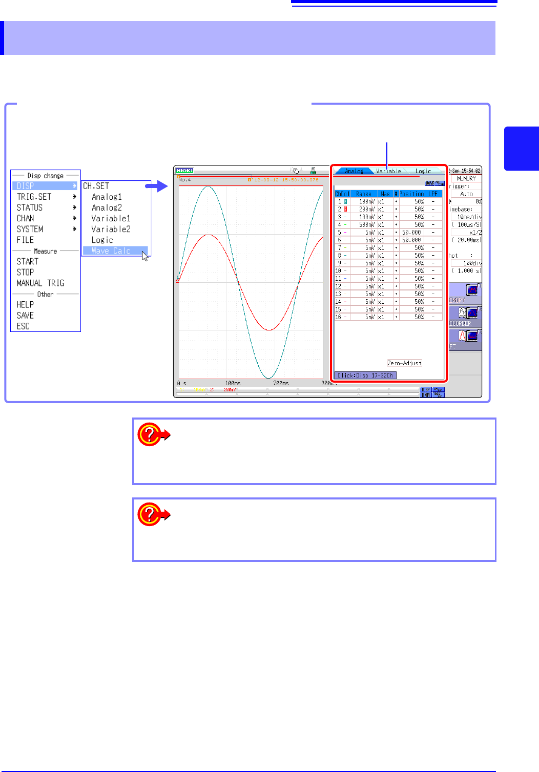
Opening the Channel settings window
You can switch setting
screens by clicking a tab.
Click [DISP]→ [CH.SET] in the
right-click menu.
To hide waveform interpolation
Set the waveform display color in the channel setting window to Off.
See: "1. Waveform Display Color" (p.76)
To copy the settings of one channel to another
See: "7.8 Copying settings to other channels (calculation No.) (Copy func-
tion)" (p.160)
3.5 Input Channel Setting
74
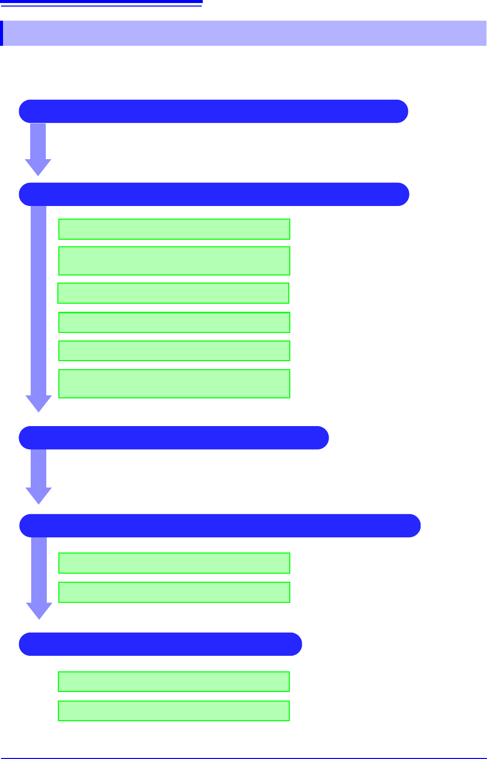
Explains the workflow to make settings for the analog channels (MR8740: Ch1 - Ch32, MR8741:Ch1 -
Ch16).
3.5.1 Channel Setting Workflow
2 Make input and screen display related settings
Make filter settings (if noise occurs)
Select input coupling
Match range to measurement target input value
(as necessary)
See:
"3. Coupling" (p.76)
"2. Vertical axis (Voltage axis) Range" (p.76)
"7.4 Converting Input Values (Scaling Func-
tion)" (p.148)
"7. Low-pass filtering" (p.78)
3 Make trigger settings (as necessary)
4 Make display color and display position settings
See:
"Chapter 8 Trigger Settings" (p.189)
1 Select the channels to use (Memory function) only)
Convert input value (as necessary)
Fine-tune waveform amplitude (as necessary)
Set zoom on vertical axis (voltage axis) direction
(as necessary)
"5. Vernier" (p.77)
"4. Vertical axis (Voltage axis) Zoom" (p.77)
Set waveform display color
Set display position and scaling (as necessary)
See:
"1. Waveform Display Color" (p.76)
"7.5 Variable Function (Setting the Waveform
Display Freely)" (p.155)
4 Make graph display settings
For 1, 2, 4, 8, 16 screens
For X-Y1, X-Y4 screens
See:
"Analog Channel Assignment" (p.72)
Procedures "4" and “5” of "6.4 Performing
Waveform X-Y Synthesis" (p.128)
3.5 Input Channel Setting
75
3
Chapter 3 Measurement Procedure
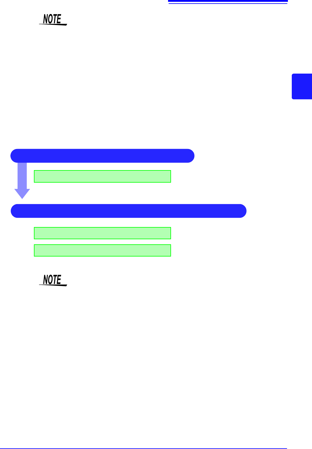
The setting workflow for logic channels (standard LOGIC terminals LA - LB (MR8740), LA -LD
(MR8741), expansion LOGIC terminals L1A - L8D) is explained below.
• When input coupling is set to GND, the waveform will have no amplitude and
range setting is not possible.
• Due to the influence of filter attenuation, correct range setting may sometimes
not be possible.
• When making trigger settings, set the vertical axis (voltage axis) range first. If
the range is changed after specifying the trigger, the trigger setting may
change.
• When using the Variable function, set the vertical axis (voltage axis) range first.
If the range is changed after specifying the Variable setting, observation with
sufficient precision may not be possible.
• When using the Variable and Scaling functions together, make the Scaling set-
tings first. If Scaling settings are made after selecting the Variable function, the
intended display result may not be achieved.
1 Make screen display related settings
Setting logic recording width
See:
"1. Logic Width" (p.79)
2 Make display color and display position settings
Set waveform display position
Set waveform display color
See:
"2. Waveform Display Position" (p.79)
"3. Waveform Display Color" (p.79)
• Waveform display position can be specified in 1% increments.
• Not displayed for X-Y1 and X-Y4 screens.
• With MR8740, install the logic units on unit 1 to unit 8. Any logic units installed
on units 9 and after will be invalid.