MR8740、MR8741_user_manual_eng_20191016H.pdf - 第353页
16.2 External I/O (MR8741 Only) 341 13 Chapter 16 External Control (MR8741 Only) 15 16 You can output a signal when a trigger event occurs. In addition, multiple MR8741s can be used for parallel synchronous operation . 1…
16.2 External I/O (MR8741 Only)
340
This applies to only the Memory function of MR8741.
The sampling speed can be controlled by applying an external signal.
1. Connect the cables for the corresponding output signals to SMPL and GND terminals.
2. On the SYSTEM screen, open the [Environment] sheet and move the cursor to
the [EXT.SMPL] item.
3. Select whether the sampling event occurs on the rising edge () of the waveform
or the falling edge (
).
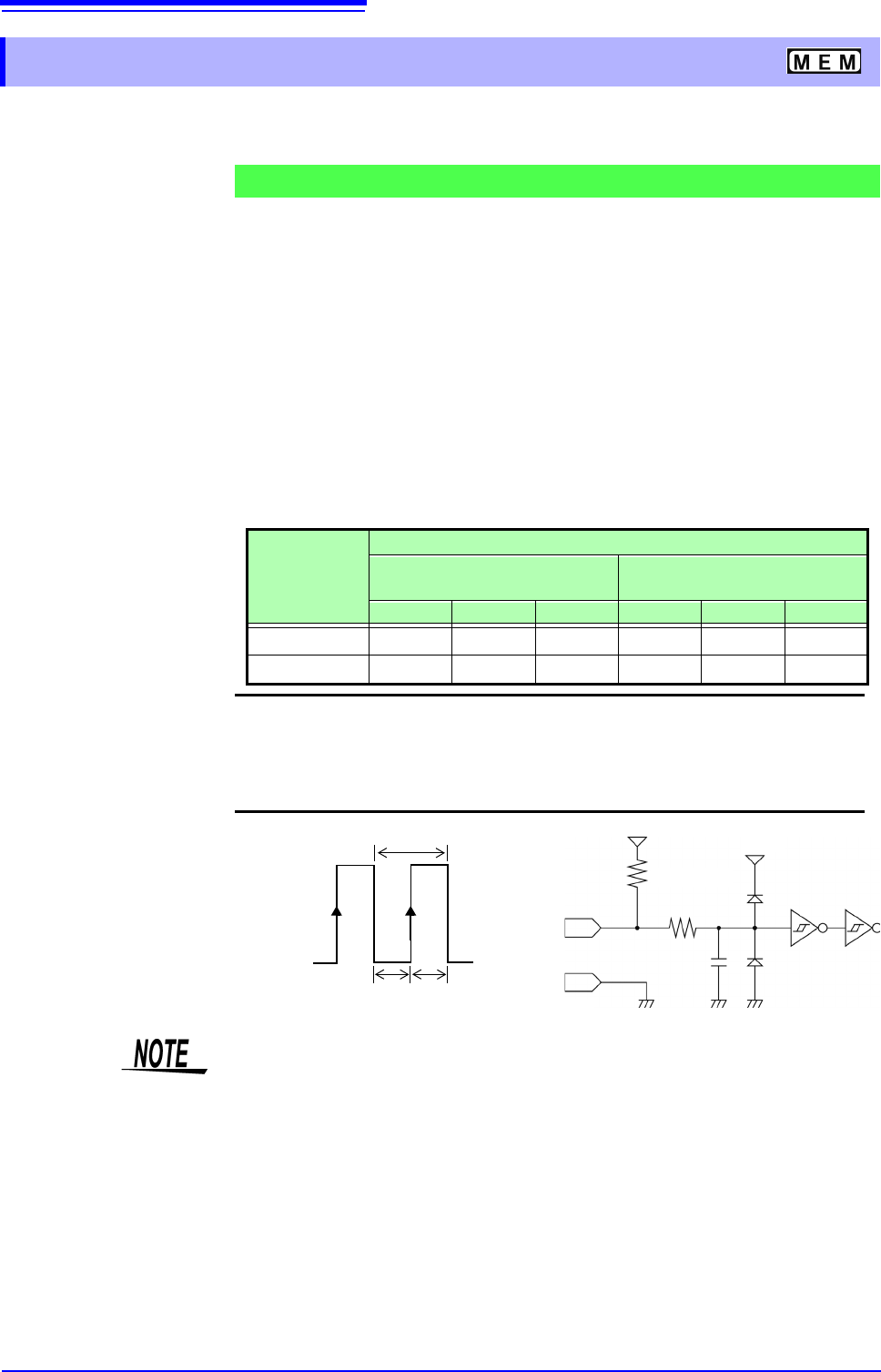
4. Input HIGH level (3.0 to 5.0 V) and LOW level (0 to 0.8 V) pulse waves or rectan-
gular waves to the EXT.SMPL terminal.
Data is sampled on the rising edge or falling edge of the input waveform. Note
that the sampling frequency is limited by the selected edge.
For proper operation, pulse width must be at least as shown in the following table.
16.2.3 External Sampling (SMPL)
Signal Input Procedure
Minimum external sampling pulse width
Setting
(EXT.SMPL)
Pulse width
When the Roll Mode is set to
[On]
When the Roll Mode is set to
[Off]
t
H
t
L
t t
H
t
L
t
> 5 s> 5 s> 10 s > 50 ns > 50 ns > 100 ns
> 5 s> 5 s> 10 s > 50 ns > 50 ns > 100 ns
Voltage range HIGH level: 3.0 to 5.0 V, LOW level: 0 to 0.8 V
Pulse width HIGH, LOW level: 50 ns or greater
Response frequency 10 MHz or lower
Maximum input voltage
-0.5 to 7 V
HIGH
3.0 to 5.0 V
SMPL
LOW
0 to 0.8 V
100
150 pF
5 V
GND
t
t
L
t
H
t
H
> 50 ns t
L
> 50 ns t
> 100 ns
3.3 k
5 V
• When a sampling signal of 5 MHz or greater is input, trigger points are
delayed by 1 sample.
• When set to [Auto] or [On], the Roll Mode can be used with external sam-
pling. However, it is disabled if the external sampling input is faster than 100
kHz, to avoid degraded sampling accuracy.
• The anti-aliasing filter (A.A.F) is disabled regardless of its setting.
See:"7.9.1 Setting the Anti-aliasing Filter (A.A.F)" (p.162)
• When Roll Mode is set to ON, externally sampled signals will not be accepted
for the following periods:
(1) 150 s to 200 s after the first sampling clock has been entered, and
(2) Clock 2 when no signals are detected in the period (1) above.
• When external sampling is valid, the output settings of Models MR8790,
MR8791, and U8793 can not be updated.
16.2 External I/O (MR8741 Only)
341
13
Chapter 16 External Control (MR8741 Only)
15
16
You can output a signal when a trigger event occurs. In addition, multiple MR8741s can be used for
parallel synchronous operation.
1. Connect the cables for the output signals to TRIGOUT and GND terminals.
See: "16.1 Connecting External Control Terminals (MR8741 Only)" (p.336)
2. On the SYSTEM screen, open the [Environment] sheet and move the cursor to
the [TRIG.OUT] item.
3. Select the output signal type for the trigger output terminal.
Select
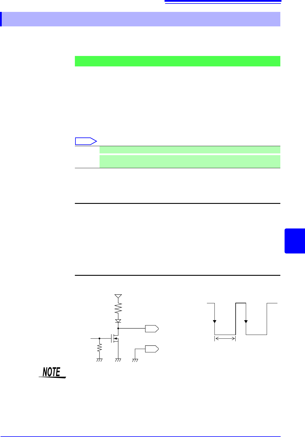
4. When trigger event occurs, a pulse wave changing from the HIGH level (4.0 to
5.0 V) to the LOW level (0 to 0.5 V) is output from the TRIG OUT terminal.
*
: Triggering should occur when the signal voltage level changes from HIGH to LOW.
16.2.4 Trigger Output (TRIG OUT)
Signal Output Procedure
Pulse After LOW level output, the signal goes HIGH after a specified interval.
Level
After the trigger is established, a LOW level signal will be outputted during the waveform
retrieval.
Output signal Open drain output (with voltage output), active LOW
*
Output voltage
range
HIGH level: 4.0 to 5.0 V, LOW level: 0 to 0.5 V
(current value:15 mA)
Pulse width Pulse width at pulse setting time : 2 ms ± 1 ms
Pulse width at level setting time: (sampling rate × no. of data
points after trigger) or more
Maximum input
voltage
50 VDC, 50 mA, 200 mW
HIGH
4.0 to 5.0 V
LOW
0 to 0.5 V
GND
TRIG OUT
10 k
10 k
5 V
1 ms or
greater
When using memory division, the trigger output (TRIG_OUT terminal output)
may output the Low level or output erratically in the following conditions.
• The time axis range is 5 s/div to 100 s/div
• The record (measurement) time is 5 ms or less
• Tracking wave display is [OFF].
16.2 External I/O (MR8741 Only)
342
You can input external signals as trigger sources. In addition, multiple MR8741s can be used for
parallel synchronous operation.
1. Connect the cables for the corresponding external input signals to the EXT.TRIG
and GND terminals.
See: "16.1 Connecting External Control Terminals (MR8741 Only)" (p.336)
2. In the Trigger Settings window, set External trigger to [On].
3. On the SYSTEM screen, open the [Environment] sheet and move the cursor to
the [EXT.TRIG] item.
4. Select whether the trigger event occurs on the rising edge () of the waveform or
the falling edge (
).
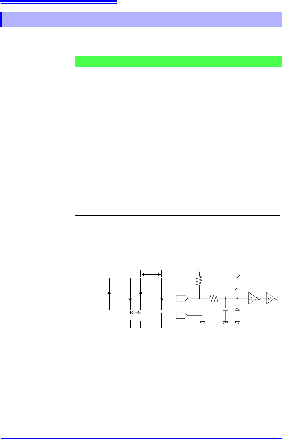
5. Short-circuit the EXT.TRIG terminal and GND, or input a HIGH level (3.0 to 5.0
V) or LOW level (0 to 0.8 V) pulse wave or rectangular wave to the EXT.TRIG
terminal.
A trigger event occurs on the rising or falling edge of the input waveform.
16.2.5 External Trigger terminal (EXT.TRIG)
Signal Input Procedure
Output signal HIGH level: 3.0 to 5.0 V, LOW level: 0 to 0.8 V
Pulse width HIGH level: 50 ns or greater, LOW level: 50 ns or greater
Maximum input
voltage
-0.5 to 7 V
HIGH
3.0 to 5.0 V
LOW
0 to 0.8 V
50 ns or greater
50 ns or greater
GND
150 pF
100
3.3 k
5 V
EXT.TRIG
[ ] [ ]
[ ]: Rising setting [ ]: Falling setting
[ ][ ]
5 V