MR8740、MR8741_user_manual_eng_20191016H.pdf - 第49页
2.1 Installing and Removing Modules 37 2 Chapter 2 Measurement Prep arations About channel allocation Information about the module s installed the instrument can be verified in the System Configuration list (p.346). MR87…
2.1 Installing and Removing Modules
36
Read "Handling the Instrument and Modules" ( p.9) carefully.
Modules specified at the time the instrument is ordered are supplied preinstalled. Use the following
procedures to add or replace modules, or to remove them from the instrument.
2.1 Installing and Removing Modules
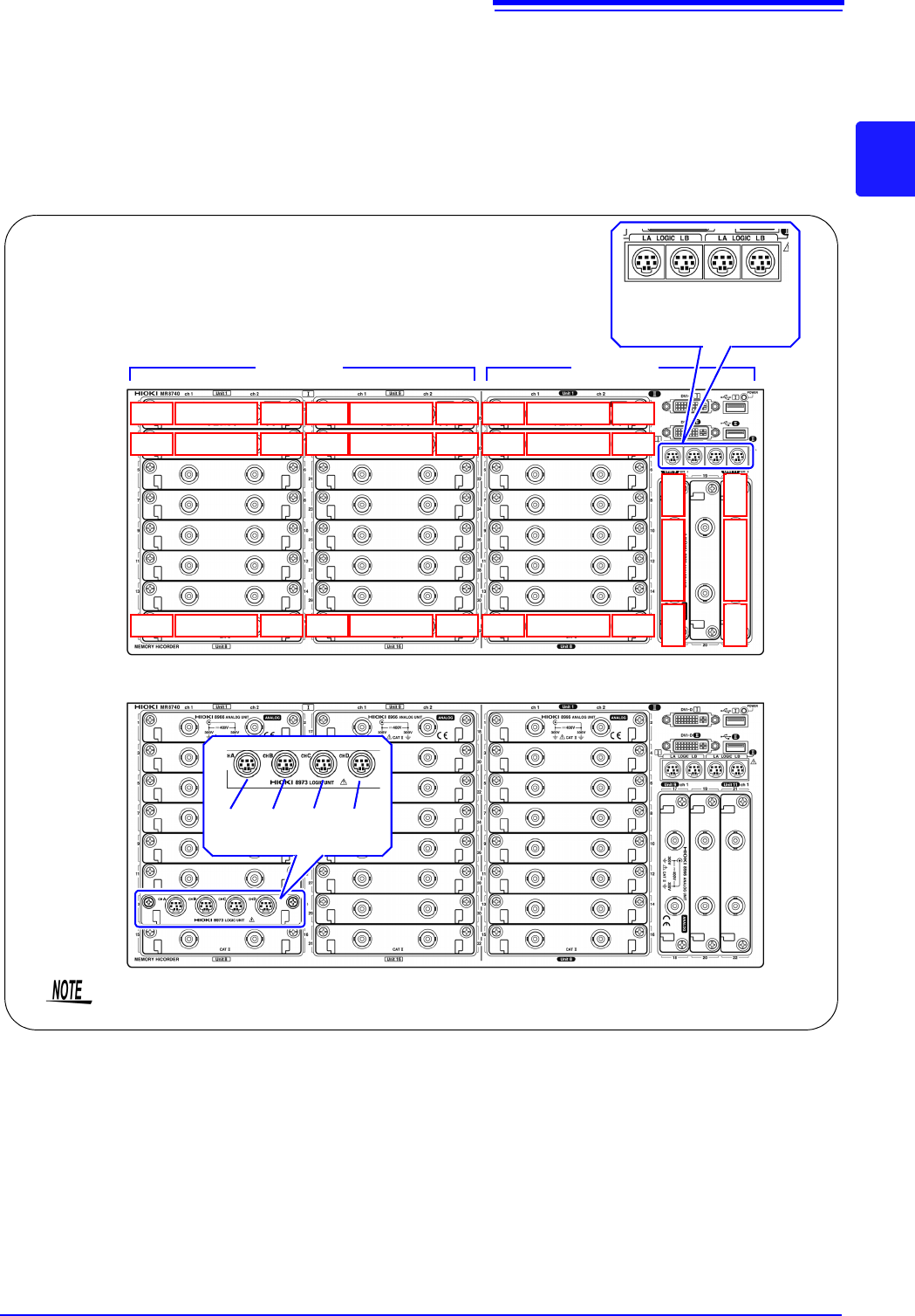
•Up to three logic units can be installed as units 1 to 8. Logic units installed as
the other units cannot be used. Other 8973 Logic Unit being installed will be
disabled.
• For information on the analog channel resolution when logic channels are
used, see "7.9 Setting Details of Modules" (p.161).
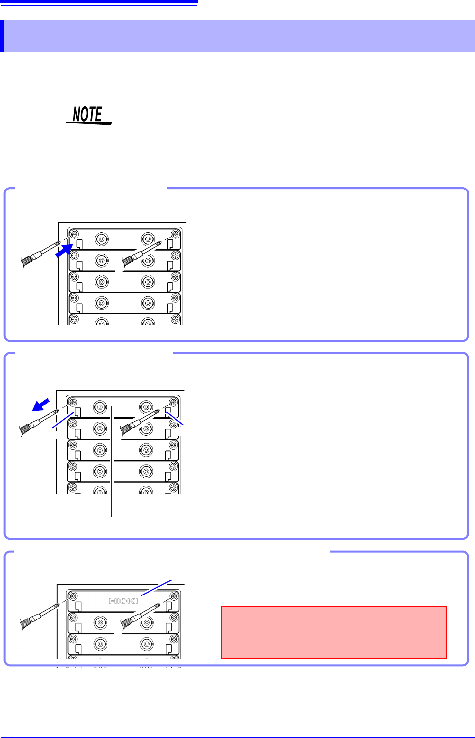
Required item: One Phillips-head screwdriver
1
Turn the instrument's POWER switch Off.
2
With attention to the orientation of the module, in-
sert it firmly all the way in.
Make certain that the labels on the module's panel face
the same direction as the labels on the right side of the in-
strument.
3
Using the Phillips screwdriver, tighten the two mod-
ule mounting screws.
Installing a module
Front Side
Handle
(Example:8966)
Handle
Required item: One Phillips-head screwdriver
1
Turn the instrument’s POWER switch Off.
2
Remove any cables or thermocouples connected to
the module.
3
Remove the power cord.
4
Using the Phillips screwdriver, loosen the two mod-
ule mounting screws.
5
Grasp the handle and pull the module out.
Removing an module
Front Side
Blank panel
Measurements made without a blank panel
installed may fail to meet specifications because
of temperature instability within the instrument.
Front Side
Using the Phillips screwdriver, tighten the two mount-
ing screws.
If not installing another module after removal
2.1 Installing and Removing Modules
37
2
Chapter 2 Measurement Preparations
About channel
allocation
Information about the modules installed the instrument can be verified in the
System Configuration list (p.346).
MR8740 The instrument has a two-block configuration consisting of Block I and Block II.
For each block, the module numbers are in order starting with one at the top, and
the channel numbers are in order starting with one on the left of the module at
the very top.
Analog channels only
Block I Block II
LA LB LA LB
[1:4] [1:4] [1:4] [1:4]
Mix including logic units
L7A L7B L7C L7D
[1:4] [1:4] [1:4] [1:4]
Install the logic units at the module 1 to module 8 positions on both blocks. Even if you
install logic units for module 9 and after, they will be invalid.
Ch1
Module 1
Ch2
Ch3
Module 2
Ch4
Ch15
Module 8
Ch16
Ch17
Module 9
Ch18
Ch19
Module 10
Ch20
Ch31
Module 16
Ch32
Ch17
Module 9
Ch18
Ch21
Module 11
Ch22
Block I Block II
Ch1
Module 1
Ch2
Ch3
Module 2
Ch4
Ch15
Module 8
Ch16
2.1 Installing and Removing Modules
38
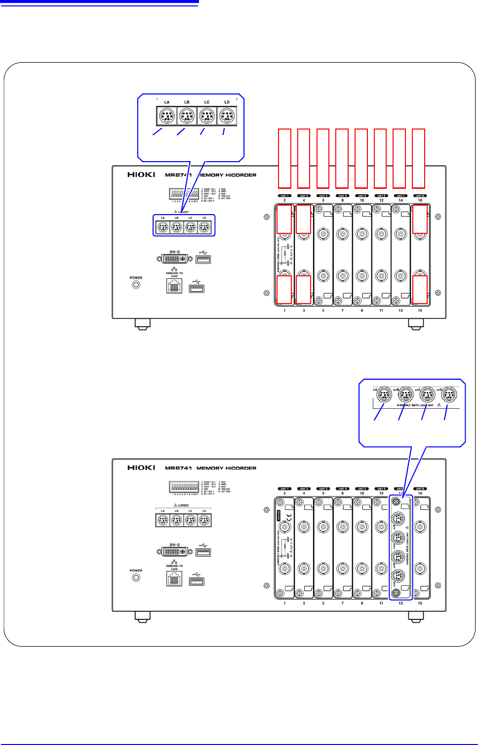
MR8741 The module numbers are in order starting with one at the left, and the channel
numbers are in order starting with one at the bottom of the module at the very
left.
Analog channels only
Ch1 Ch2
LA LB LC LD
[1:4] [1:4] [1:4] [1:4]
Module 1
Module 2
Module 3
Module 4
Module 5
Module 6
Module 7
Module 8
Mix including logic units
Ch3 Ch4
Ch15 Ch16
L7A L7B L7C L7D
[1:4] [1:4] [1:4] [1:4]