MR8740、MR8741_user_manual_eng_20191016H.pdf - 第173页
7.9 Setting Details of Modules 161 6 Chapter 7 Utility Functions 7 Using the [Each Ch] sheet accessed from the Channel sc reen, you can make detailed settings. Logic channel allocat ion when using S tan dard LOGIC termin…
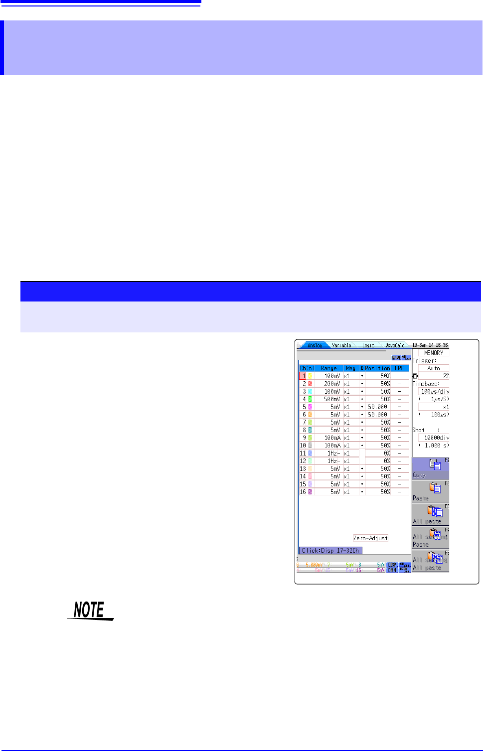
7.8 Copying settings to other channels (calculation No.) (Copy function)
160
At the following screens, settings can be copied to other channels and calculation No. (When the
FFT function is used).
• Channel settings window
• Display range window
• Trigger settings window
• Status screen-[Status] sheet- [Analysis] list and [Scale] list (with FFT func-
tion only)
• Status screen - [Num Calc] sheet
• Status screen-[Wave Calc] sheet
• Channel screen - [Unit List] sheet
• Channel screen - [Scaling] sheet
• Channel screen - [Comment] sheet
The procedure is explained for the Display range window.
7.8 Copying settings to other channels (calcula-
tion No.) (Copy function)
Procedure
To open the screen: Right-click and select [DISP] Waveform screenRight-click and select
[CH.SET]
Display range window
1
Click the copy source channel number (calculation
No.).
2
Select [Copy].
3
Click the channel number (calculation No.) where you
want to paste the settings.
4
Select [Paste].
To copy to all channels (calculations), select a chan-
nel number (calculation No.) other than the copy
source and select [All Paste].
When you want to copy all the settings on the Unit list/
Scaling/Variable sheets, select the [All setting
Paste] button or [All setting All paste] button.
When channel settings are copied among different model units, the settings
other than scaling cannot be performed. (Scaling copy is available.)
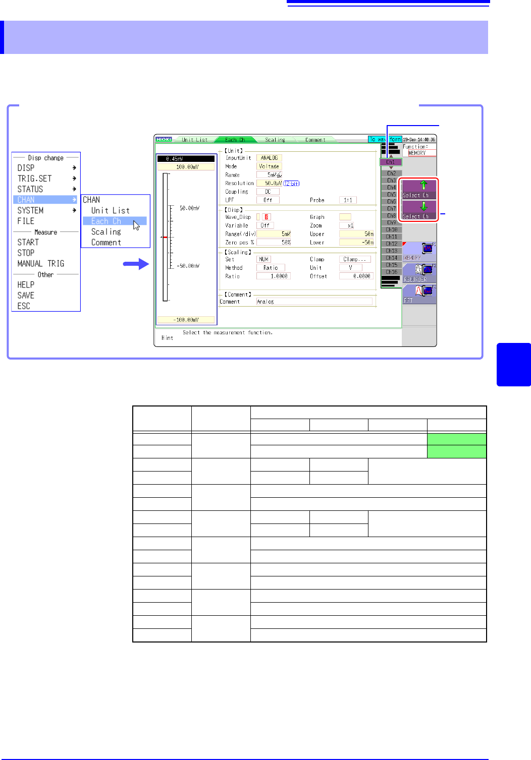
7.9 Setting Details of Modules
161
6
Chapter 7 Utility Functions
7
Using the [Each Ch] sheet accessed from the Channel screen, you can make detailed settings.
Logic channel allocation when using Standard LOGIC terminals
*: Ch1 - Ch2 provide 12-bit precision when logic channels LA - LB are used.
When Ch1 to Ch2 are 8970 Freq Unit and standard logic channels LA to LB are
used, the units of corresponding channels can no longer be used.
When the MR8990 Digital Voltmeter Unit is installed on unit 1 (unit 1 or unit 2 in
the case of MR8741), the standard logic can no longer be used.
7.9 Setting Details of Modules
Select
the
channel.
Shows
the chan-
nel num-
ber and
channel
position.
Opening the [Each Ch] sheet, Making a Channel Selection
Click [CHAN] in the right-
click menu.
Module
Memory for each channel (16 bits)
4 bits 4 bits 4 bits 4 bits
Ch1*
Analog
Analog Ch1
LA
Ch2* Analog Ch2
LB
Ch3*
Logic
L2A L2B
-
Ch4* L2C L2D
Ch5
Analog
Analog Ch5
Ch6 Analog Ch6
Ch7
Logic
L4A L4B
-
Ch8 L4C L4D
Ch9
Analog
Analog Ch9
Ch10 Analog Ch10
Ch11
Analog
Analog Ch11
Ch12 Analog Ch12
Ch13
Analog
Analog Ch13
Ch14 Analog Ch14
Ch15
Analog
Analog Ch15
Ch16 Analog Ch16
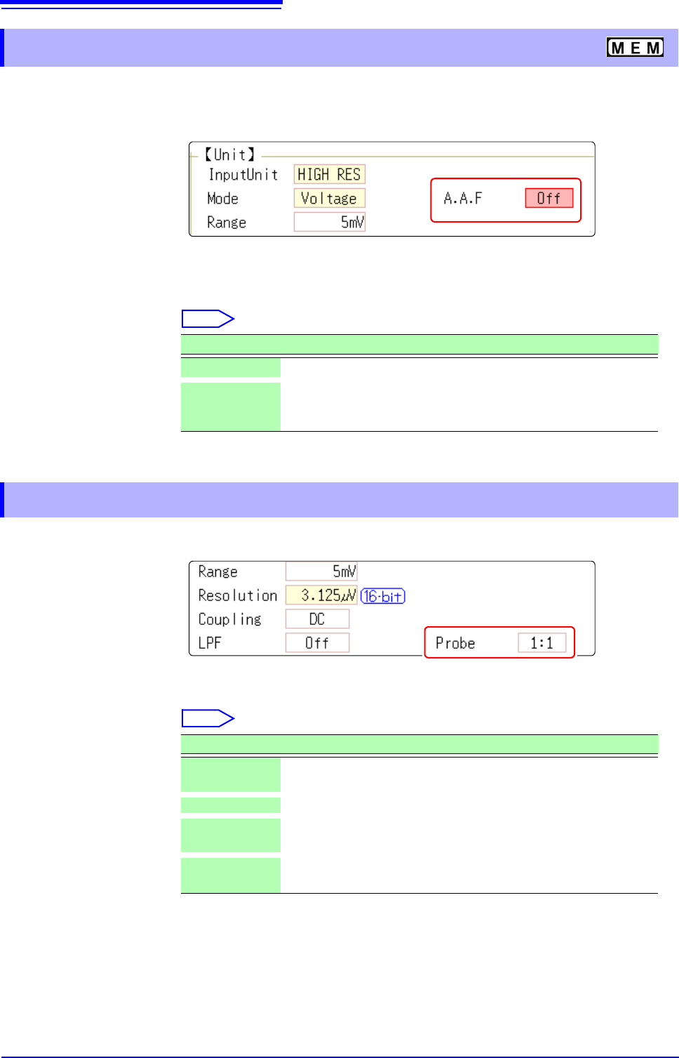
7.9 Setting Details of Modules
162
The anti-aliasing filter (A.A.F) setting is configurable for Model 8968 High Resolution Unit and Model
U8979 Charge Unit only.
See: Opening the [Each Ch] sheet, Making a Channel Selection (p.161)
A.A.F Enable the anti-aliasing filter to remove aliasing distortion.
The cutoff frequency automatically changes according to the time axis range or
(when the FFT function is used) the frequency range setting.
Select
See: Opening the [Each Ch] sheet, Making a Channel Selection (p.161)
Probe Make the setting when performing measurement with a connection cable or
probe.
Select
7.9.1 Setting the Anti-aliasing Filter (A.A.F)
Selections Description
Off
The anti-aliasing filter is disabled. (default setting)
On The anti-aliasing filter is enabled.
(When the External sampling is used, the antialiasing filter (AAF) is
not available.)
7.9.2 Probe Attenuation Selection
Selections Description
1:1
Model L9197, L9198 or L9217 Connection Cable connected to the
module. (default setting)
10:1 Model 9665 10:1 Probe connected to the module.
100:1
9666 100:1 Probe, P9000-01/-02 Differential Probe connected to
the module.
1000:1
Model 9322 Differential Probe, P9000-01/-02 Differential Probe
connected to the module.