MR8740、MR8741_user_manual_eng_20191016H.pdf - 第210页
8.4 Triggering by Logic Signals (Logic Trigge r) 198 3. T rigger Pattern Make the settings of the logic trigger pattern. Select Setting Example Example 1: T rigger when the input sign al matches any of the following cr i…
8.4 Triggering by Logic Signals (Logic Trigger)
197
7
Chapter 8 Trigger Settings
8
The steps for making settings and selecting the type of logic trigger are described below.
The Trigger settings window ([Logic Trig] sheet) is used.
• Input signals on logic channels serve as the trigger source. Triggering occurs
when the specified trigger pattern and logical probe combining criteria (AND/
OR) are met.
• The trigger detection method can be selected according to whether a trigger is
applied or not when the criteria are already met at the start of measurement.
• By using the trigger filter, triggering can be limited so as to occur only when
trigger criteria are met for at least the specified filter width.
1. Trigger Sets the trigger probe combining logic (AND/OR).
Select
2. Filter Sets the filter width (trigger filter) for triggering. (as occasion demands)
Suppresses triggering from noise.(p.195)
Select
8.4 Triggering by Logic Signals (Logic Trigger)
Procedure
To open the screen: Right-click and select [DISP] Waveform screen Right-click and select [TRIG.SET]
Trigger settings window ([Logic Trig] sheet)
1
Move the flashing cursor to the channel you want
to set.
2
Make the setting from the GUI displayed on the
screen.
1. 2. 3.
Logic Channels
Off Logic triggering is disabled. (default setting)
OR
Triggering occurs when input signal logic matches any set-
ting in the trigger pattern.
AND
Triggering occurs only when input signal logic matches all
settings in the trigger pattern.
Off
Trigger filtering is disabled. (default setting)
0.1 to 10
Trigger filtering is enabled.
The filter width is set as a number of divisions.
8.4 Triggering by Logic Signals (Logic Trigger)
198
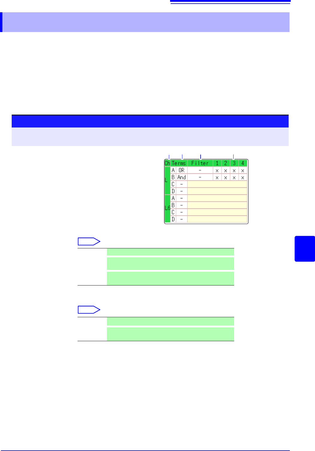
3. Trigger Pattern Make the settings of the logic trigger pattern.
Select
Setting Example Example 1: Trigger when the input signal matches any of the following cri-
teria:
Channel 1 (LA1): HIGH level
Channel 2 (LA2): LOW level
Trigger: OR
LA [1, 2, 3, 4]: [1 0 X X ]
Triggering occurs when the LA1 or LA2 trig-
ger criteria are met.
Example 2: Triggering occurs when the
input signal matches both of the following criteria:
Channel 1 (LA1): HIGH level
Channel 2 (LA2): LOW level
Trigger: AND
LA [1, 2, 3, 4]: [1 0 X X ]
X
Ignore signal. (default setting)
0
Trigger at LOW signal level.
1
Trigger at HIGH signal level.
To copy the setting to another channel
The Trigger settings window ([Logic Trig] sheet) can be used to copy a setting.
See:"7.8 Copying settings to other channels (calculation No.) (Copy function)" (p.160)
Trigger Pattern
T
LA1 1
LA2 0
LA3 X
LA4 X
Trigger Pattern
T
LA1 1
LA2 0
LA3 X
LA4 X
T
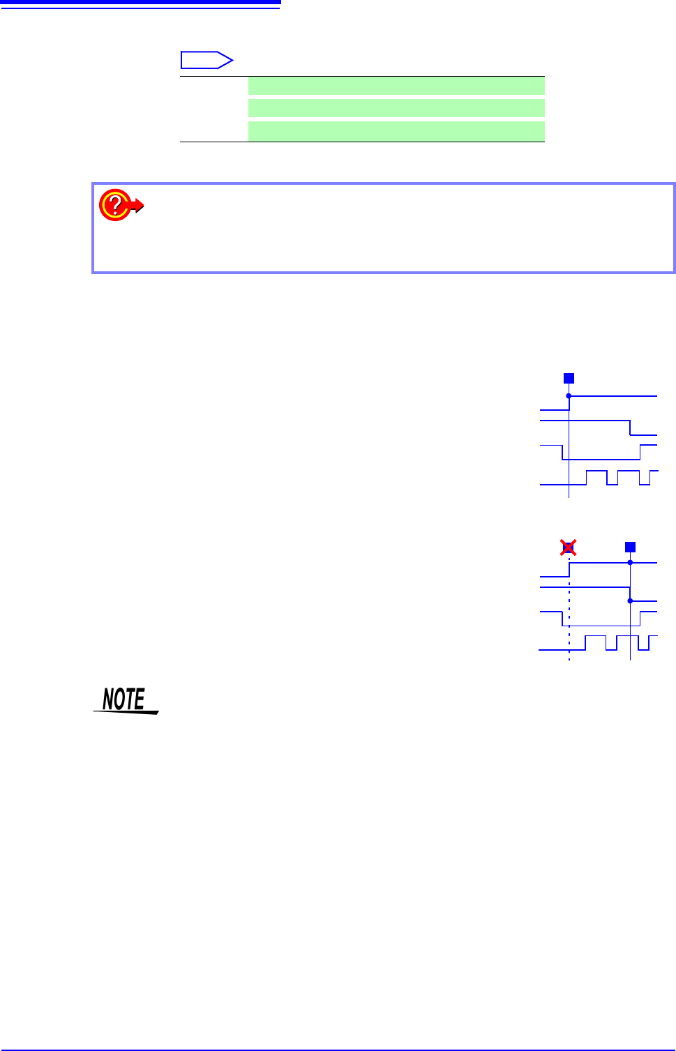
• If the conditions are met already when measurement is started (AND: all trig-
ger patterns are met, OR: one trigger pattern is met), triggering does not occur.
Triggering only occurs if the conditions are removed and then met again.
• Triggers for standard logic channels (LA and LB) are enabled regardless of the
logic waveform display or unit type.
8.5 Trigger by Timer or Time Intervals (Timer Trigger)
199
7
Chapter 8 Trigger Settings
8
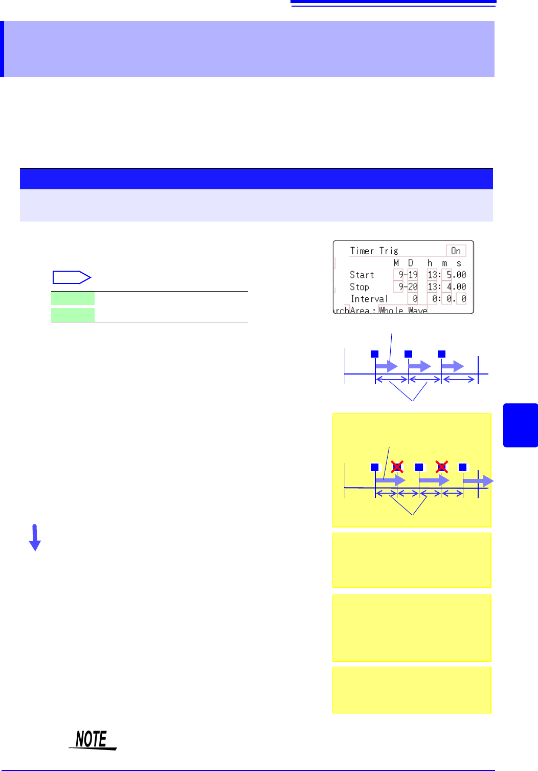
Set this to record at fixed times.
• Triggering occurs at the specified interval from the specified Start time until the
Stop time.
• Before setting, verify that the clock is set to the correct time. If not, set the
clock on the System screen - Init sheet. (p.57)
8.5 Trigger by Timer or Time Intervals
(Timer Trigger)
The timer trigger time and the time at which the trigger is actually fired may differ
by up to 3 sample times.
1
2
3
Procedure
To open the screen: Right-click and select [DISP] Waveform screen Right-click and select [TRIG.SET] Trigger
settings window
1
Enable or disable the timer trigger.
Move the flashing cursor to the [Timer Trig] item.
Select
2
(When [On] is selected)
Set Start and Stop times.
Move to cursor to the [M], [D], [h] and [m] items to set
recording Start and Stop times.
Set the date and time.
To set the current date and time:
Select [Present Time].
3
(To apply a trigger through the specified interval, from
Start to Stop)
Set the Interval.
Move to cursor to the [D], [h], [m] and [s] items of [Interval].
Set the recording interval.
Recording starts at the specified Start time.
To stop recording early:
Click [STOP] in the right-click menu.
Off
Timer triggering is disabled.
On
Timer triggering is enabled.
Start Time
Stop Time
T T T
Interval
Records the specified recording length
START
Start Time
Stop Time
T T T
Interval
Records the specified recording length
T T
When the specified interval is shorter
than the specified recording length:
START
When the interval is set to zero
If the [Repeat] trigger mode is selected, or
REC&MEM function is used, recording is
repeated from Start to Stop times.
When the recording length exceeds the
specified interval
The next trigger is not applied until the
data for the specified recording length has
been acquired.
When the recording length exceeds the
stop time
Recording time depends on the operating
function.
"About Stop Time and Recording Length"
(
p.200)