MR8740、MR8741_user_manual_eng_20191016H.pdf - 第17页
Safety Information 5 Symbols in This Manual Symbols Affixed to the Instrument Indicates cautions and hazards. When this symbol is prin ted on the instrument, refer to the corresponding topic in this Instruction Manual. I…
Safety Information
4
This instrument and modules are designed to conform to IEC 61010 Safety
Standards, and has been thoroughly tested for safety prior to shipment. How-
ever, using the instrument in a way not described in this manual may negate the
provided safety features.
Before using the instrument, be certain to carefully read the following safety
notes:
In this document, the risk seriousness and the hazard levels are classified as follows.
Safety Information
Mishandling during use could result in injury or death, as well as damage to the
instrument. Be certain that you understand the instructions and precautions in
the manual before use.
With regard to the electricity supply, there are risks of electric shock, heat gener-
ation, fire, and arc discharge due to short circuits. If anyone who is unfamiliar
with electrical measuring instruments will use the instrument, a person familiar
with such instruments must supervise operations.
Protective Gear
This instrument is measured on a live line. Wear the insulating protective gear
according to the regulation to avoid electric shocks.
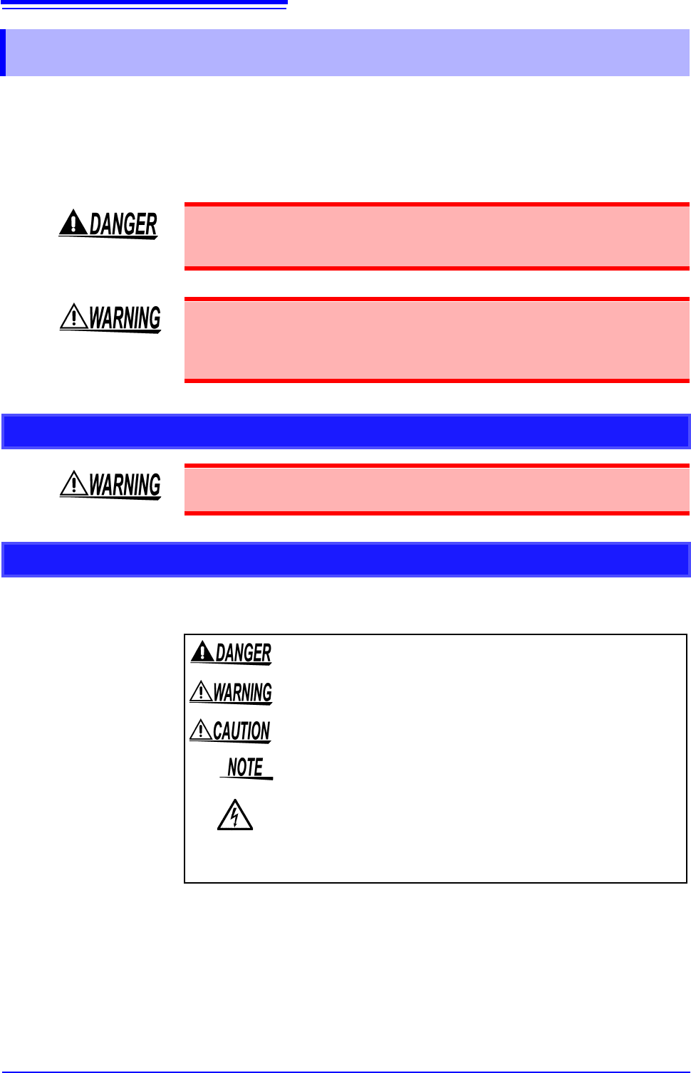
Notation
Indicates that incorrect operation presents an extreme hazard that
could result in serious injury or death to the user.
Indicates that incorrect operation presents a significant hazard that
could result in serious injury or death to the user.
Indicates that incorrect operation presents a possibility of injury to the
user or damage to the instrument.
Indicates advisory items related to performance or correct operation
of the instrument.
Indicates a high voltage hazard.
If a particular safety check is not performed or the instrument is mis-
handled, this may give rise to a hazardous situation; the operator
may receive an electric shock, be burnt or even be fatally injured.
*
Indicates that descriptive information is provided below.
Safety Information
5
Symbols in This Manual
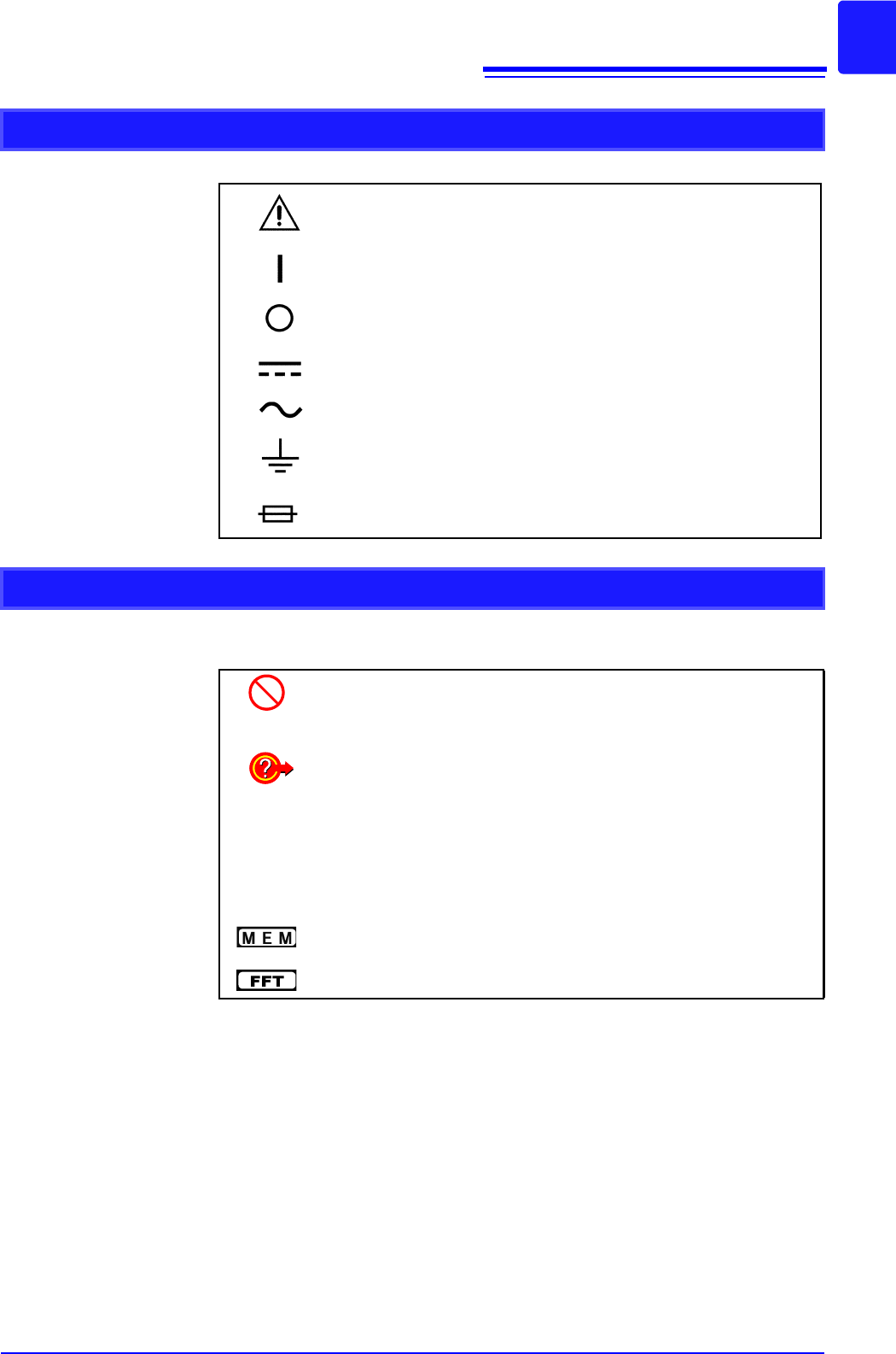
Symbols Affixed to the Instrument
Indicates cautions and hazards. When this symbol is printed on the
instrument, refer to the corresponding topic in this Instruction Manual.
Indicates the ON side of the power switch.
Indicates the OFF side of the power switch.
Indicates DC (Direct Current).
Indicates AC (Alternating Current).
Indicates a grounding terminal.
Indicates a fuse.
Other Symbols
Indicates the prohibited action.
p. )
Indicates the location of reference information.
Indicates quick references for operation and remedies for troubleshoot-
ing.
*
Indicates that descriptive information is provided below.
[ ]
Menus, commands, dialogs, buttons in a dialog, and other names on the
screen and the keys are indicated in brackets.
Unless otherwise specified, "Windows" represents Windows 7, Windows
8, and Windows 10.
Indicates Memory function support.
Indicates FFT Recorder function support.

Safety Information
6
Mouse Operations
Click: Press and quickly release the left button of the mouse.
Right-click: Press and quickly release the right button of the mouse.
Double-click: Quickly click the left button of the mouse twice.
Drag: Move the mouse while holding down the left button of the
mouse, and then release the button at the desired position.
Activate: Click on a screen to activate that screen.
Accuracy
We define measurement tolerances in terms of f.s. (full scale) values, with the following meanings:
f.s. (maximum display value or scale length)
The maximum displayable value or scale length. In this instrument, the maxi-
mum displayable value is the range (V/div) times the number of divisions (20) on
the vertical axis.
Example: For the 1 V/div range, f.s. = 20 V
rdg. (reading value, displayed value, or indicated value)
The value currently being measured and indicated on the measuring instrument.