MR8740、MR8741_user_manual_eng_20191016H.pdf - 第47页
35 2 Chapter 2 Measurement Prep arations Measurement Prep arations Cha pter 2 W ork Flow 1 Install this instrument (p.8) 2 Install or remo ve modules. (When adding or replacing modules) (p.36) 3 Connect a logic probe to …
1.5 Basic Operations
34
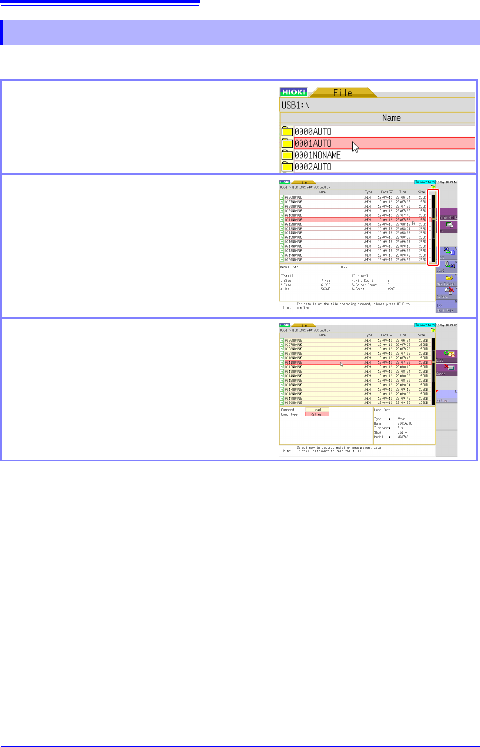
You can change the displayed folder, load files, and perform other file operations on the File screen.
1.5.7 File Operations
Moving to a folder
To move to a folder, double-click the folder to which you
want to move. To move to the folder one layer up, click
the folder path part.
Scrolling a file list
Click the bar on the right side of the screen to scroll a
list. You can also scroll the list one item at a time by
rotating the wheel button forward or backward.
Selecting the file to load
If you double-click the list, you can select the file to load.
35
2
Chapter 2 Measurement Preparations
Measurement
Preparations Chapter 2
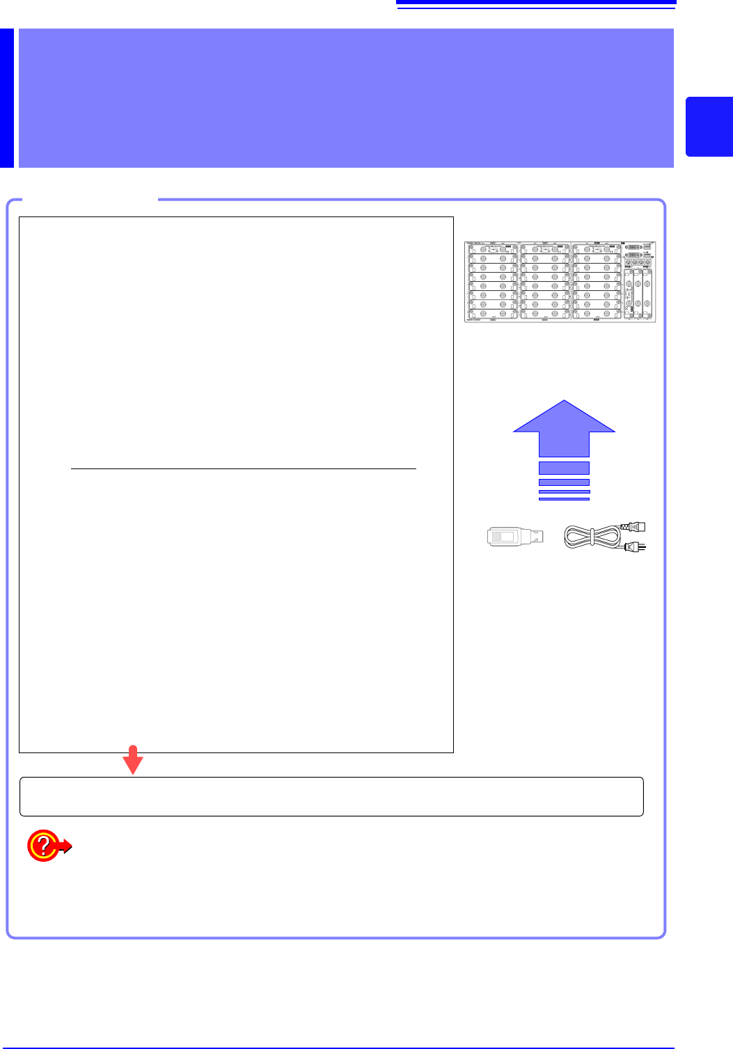
Work Flow
1
Install this instrument (p.8)
2
Install or remove modules.
(When adding or replacing modules)
(p.36)
3
Connect a logic probe to the Standard
LOGIC terminals
(When measuring logic signals)
(p.48)
4
Connect the input cable(s) to the input
module
(When measuring analog signals)
(p.39)
Probes and cables will differ depending on the measurement purpose.
5
Connect an LCD monitor
(p.18)
6
Insert media (USB memory stick)
(p.53)
7
Connect the power cord
(p.55)
8
Turn the power on
(p.56)
9
Setting the clock
(p.57)
10
Perform zero-adjust
(p.58)
When preparations are complete, let's start a measurement (p.61)
Using communication functions
See: "Chapter 15 Connection to a Computer" (p.313)
Using external control functions
See: "Chapter 16 External Control (MR8741 Only)" (p.335)
2.1 Installing and Removing Modules
36
Read "Handling the Instrument and Modules" ( p.9) carefully.
Modules specified at the time the instrument is ordered are supplied preinstalled. Use the following
procedures to add or replace modules, or to remove them from the instrument.
2.1 Installing and Removing Modules
•Up to three logic units can be installed as units 1 to 8. Logic units installed as
the other units cannot be used. Other 8973 Logic Unit being installed will be
disabled.
• For information on the analog channel resolution when logic channels are
used, see "7.9 Setting Details of Modules" (p.161).
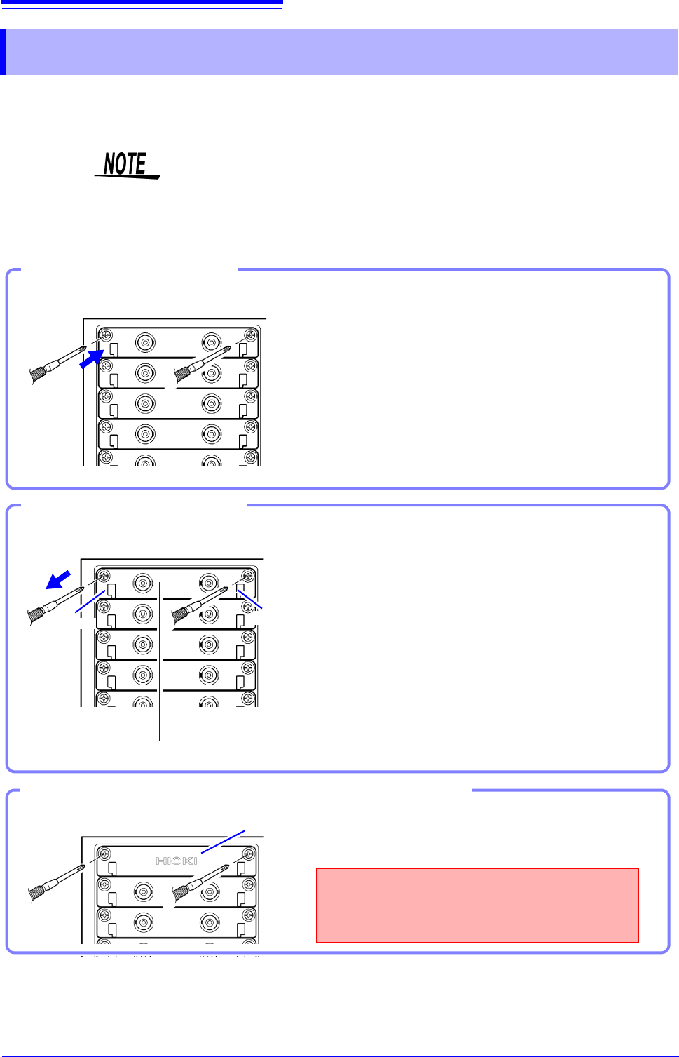
Required item: One Phillips-head screwdriver
1
Turn the instrument's POWER switch Off.
2
With attention to the orientation of the module, in-
sert it firmly all the way in.
Make certain that the labels on the module's panel face
the same direction as the labels on the right side of the in-
strument.
3
Using the Phillips screwdriver, tighten the two mod-
ule mounting screws.
Installing a module
Front Side
Handle
(Example:8966)
Handle
Required item: One Phillips-head screwdriver
1
Turn the instrument’s POWER switch Off.
2
Remove any cables or thermocouples connected to
the module.
3
Remove the power cord.
4
Using the Phillips screwdriver, loosen the two mod-
ule mounting screws.
5
Grasp the handle and pull the module out.
Removing an module
Front Side
Blank panel
Measurements made without a blank panel
installed may fail to meet specifications because
of temperature instability within the instrument.
Front Side
Using the Phillips screwdriver, tighten the two mount-
ing screws.
If not installing another module after removal