MR8740、MR8741_user_manual_eng_20191016H.pdf - 第208页
8.3 Triggering by Analog Signals 196 Description About period range settin gs The period ra nge settings for period triggering depend on the sampling per iod (sampling rate). (Cha nging the timebase also chan ges the per…
8.3 Triggering by Analog Signals
195
7
Chapter 8 Trigger Settings
8
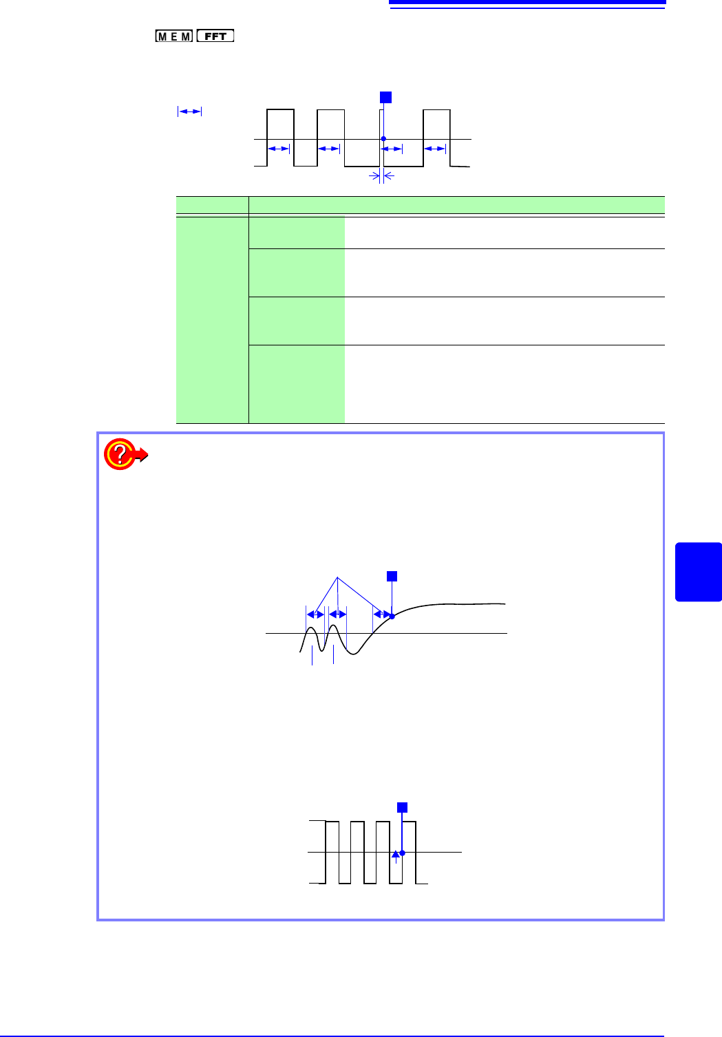
5. Glitch Trigger( only) ___________________________________
Triggering occurs when the input signal crosses the trigger level (threshold volt-
age) if its pulse width is shorter than the specified width.
Suppressing Noise Effect
Noise near the trigger level can erroneously increment the event count. Set the trig-
ger filter to avoid such effects.
Type Parameters
[Grit.]
[L] (Level) Sets the level (voltage value) for the trigger. (The setting
can be made in 1/50 increments.)
[S] (Slope) Determines whether triggering occurs when the signal
crosses the threshold (trigger level) on the upslope (rising
edge) or on the downslope (falling edge). ()
[Event]
The number of signal rising edge (or falling edge) events
is counted, and triggering occurs when the Event number
set here is exceeded. (1 to 4000)
[Width] Sets the pulse width (time) that is used to determine a
glitch. Triggering occurs when the width is lower than this
value. (The available setting range depends on the sam-
pling frequency. Lower limit: sampling frequency x 2, up-
per limit: sampling frequency x 4000)
Glitch Width
Trigger Level
Input Waveform
Trigger Slope: [
]
T
When Using Noisy Signals for Triggering
Method 1: Enable the trigger filter
By setting the filter width to prevent triggering on noise, triggering occurs only
when the trigger criteria continue to be met for at least the specified width
(interval).
Method 2: Setting an Event Count
If triggering occurs too frequently, an event count can be specified so that a
trigger is accepted only after the specified number of trigger events has
occurred.
Trigger Level
The noise does not cause triggering.
T
Trigger Point
Filter Width
2.5 V
5 V
0 V
Trigger Level
T
1234
Example: When the event count is set to [4] (Slope: )
Event Count
8.3 Triggering by Analog Signals
196
Description About period range settings
The period range settings for period triggering depend on the sampling period
(sampling rate). (Changing the timebase also changes the period setting range.)
The sampling rate setting can be verified on the Status screen - Status sheet.
The upper threshold of the period range cannot be set below the lower threshold,
and vice-versa.
Lower threshold: can be set either to zero, or to at least five times the sampling
period.
Upper threshold: can be set to no more than 2,000 times the sampling period.
To apply a trigger when the frequency increases (shorter period) above the
upper threshold:
Set the period trigger type to [Per.I], and the lower threshold to [0]. The lower
threshold is ignored, and triggering occurs when the frequency exceeds that cor-
responding to the upper threshold.
To apply a trigger when the frequency decreases (longer period) below the upper
threshold:
Set the period trigger type to [Per.O], and the lower threshold to [0]. The lower
threshold is ignored, and triggering occurs when the frequency drops below that
corresponding to the upper threshold.
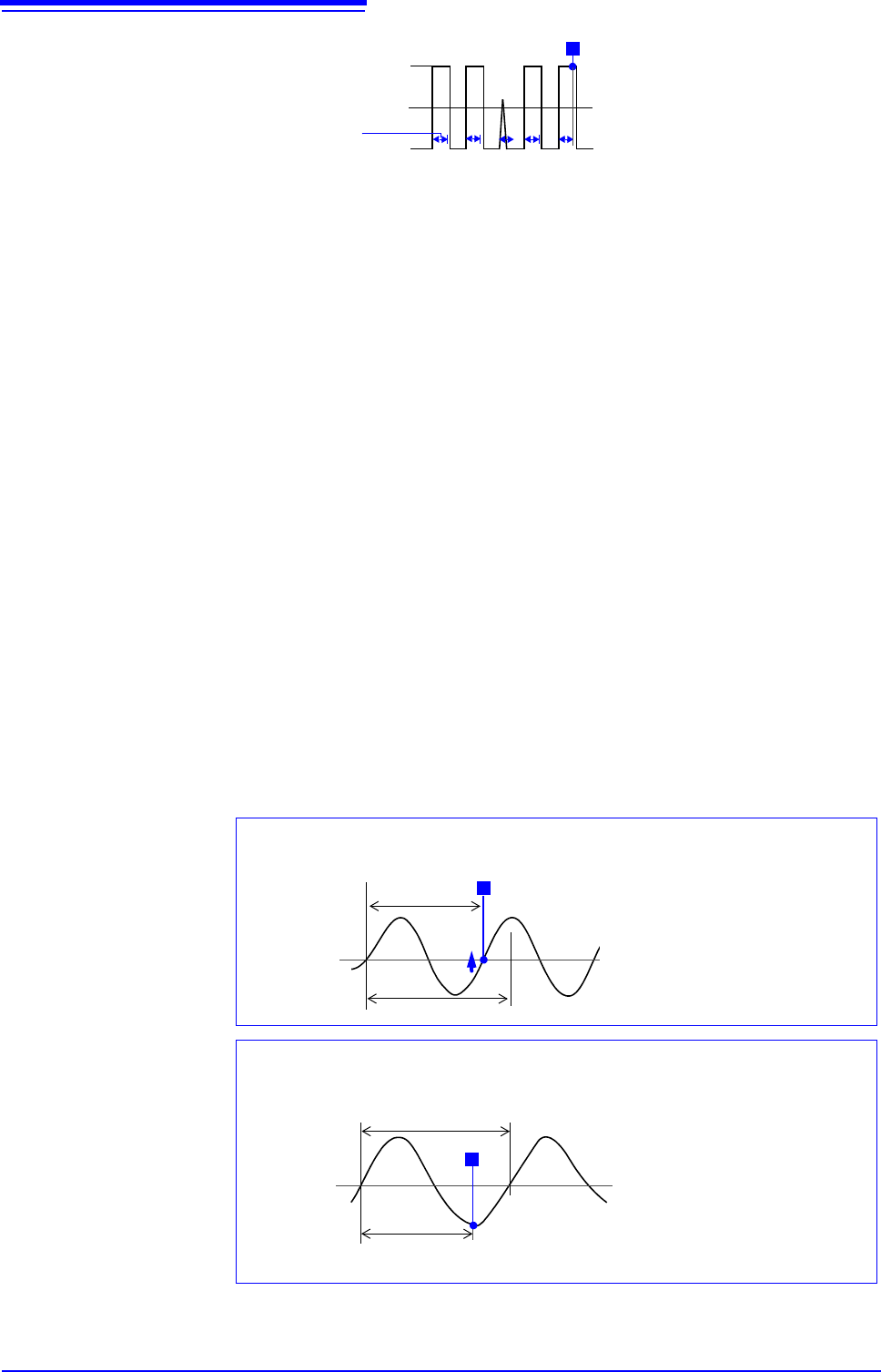
About the trigger point of the Out-of-Period trigger
Triggering occurs when the period of sequential crossings of the specified refer-
ence voltage exceeds the period range.
The point at which triggering occurs depends on the specified period range and
the period of the measured signal.
2.5 V
5 V
0 V
Trigger Level
T
12 34
Event Count
x
Filter Width
Reference
Voltage Level
Lower Threshold
Input Signal
Period
T
Triggering occurs when the rising
edge ( trigger slope) of the input
signal crosses the reference volt-
age level, before reaching the low-
er period threshold.
When the input signal period is shorter than the specified lower threshold
(Trigger Slope:
)
Reference
Voltage Level
Upper Threshold
Input Signal
Period
T
Triggering occurs when the upper
threshold period is reached, be-
fore the rising edge ( trigger
slope) of the input signal crosses
the reference voltage level.
Therefore, the trigger point is de-
termined by the upper threshold
of the period range.
When the input signal period is longer than the specified upper threshold
(Trigger Slope:
)
8.4 Triggering by Logic Signals (Logic Trigger)
197
7
Chapter 8 Trigger Settings
8
The steps for making settings and selecting the type of logic trigger are described below.
The Trigger settings window ([Logic Trig] sheet) is used.
• Input signals on logic channels serve as the trigger source. Triggering occurs
when the specified trigger pattern and logical probe combining criteria (AND/
OR) are met.
• The trigger detection method can be selected according to whether a trigger is
applied or not when the criteria are already met at the start of measurement.
• By using the trigger filter, triggering can be limited so as to occur only when
trigger criteria are met for at least the specified filter width.
1. Trigger Sets the trigger probe combining logic (AND/OR).
Select
2. Filter Sets the filter width (trigger filter) for triggering. (as occasion demands)
Suppresses triggering from noise.(p.195)
Select
8.4 Triggering by Logic Signals (Logic Trigger)
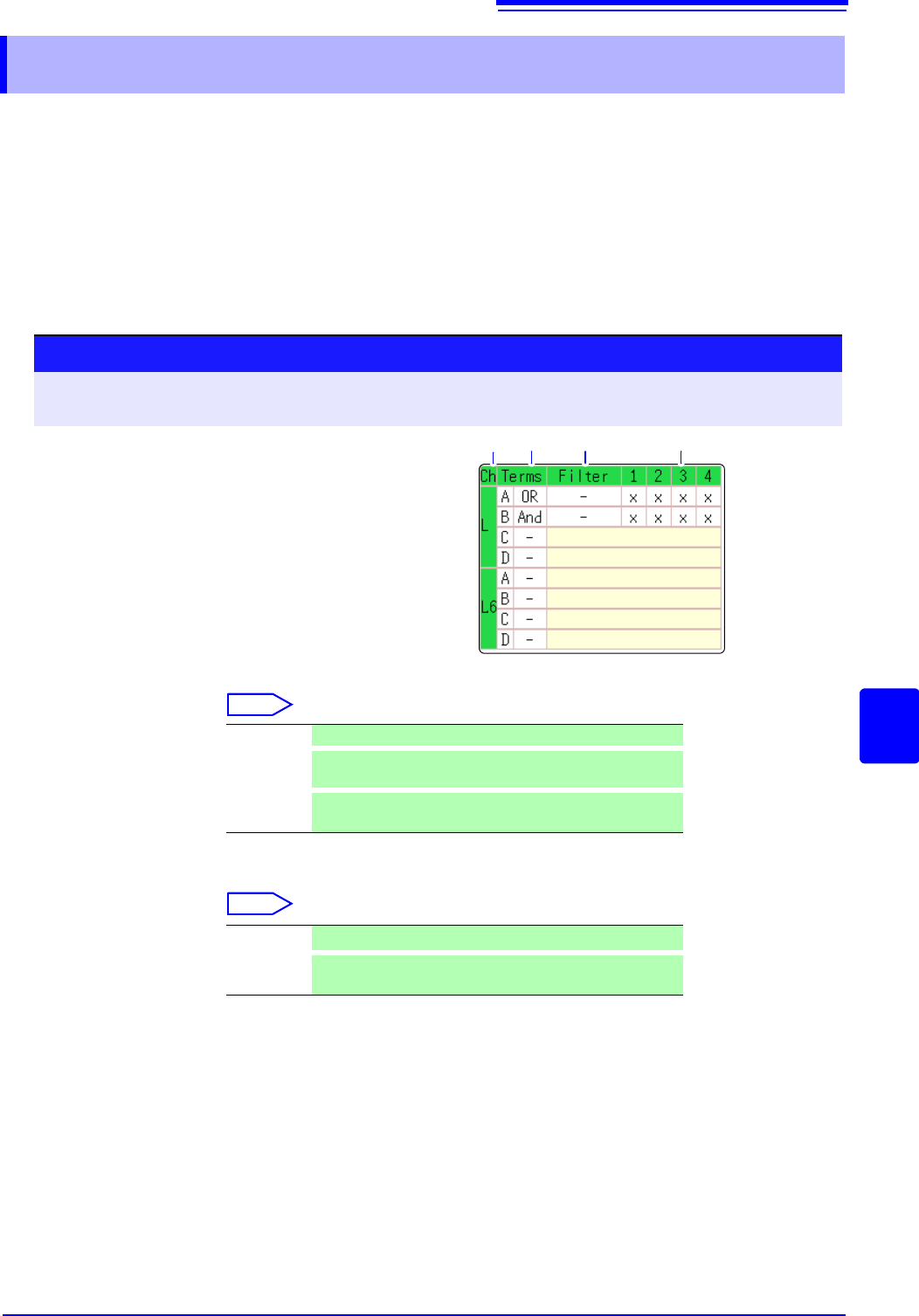
Procedure
To open the screen: Right-click and select [DISP] Waveform screen Right-click and select [TRIG.SET]
Trigger settings window ([Logic Trig] sheet)
1
Move the flashing cursor to the channel you want
to set.
2
Make the setting from the GUI displayed on the
screen.
1. 2. 3.
Logic Channels
Off Logic triggering is disabled. (default setting)
OR
Triggering occurs when input signal logic matches any set-
ting in the trigger pattern.
AND
Triggering occurs only when input signal logic matches all
settings in the trigger pattern.
Off
Trigger filtering is disabled. (default setting)
0.1 to 10
Trigger filtering is enabled.
The filter width is set as a number of divisions.