MR8740、MR8741_user_manual_eng_20191016H.pdf - 第329页
15.1 LAN Settings and Connection (Before Using FTP/Internet Browser/Command Communications) 317 12 Chapter 15 Connection to a Computer 14 15 Click [SYSTEM] in the right-click menu to display the Communications sheet. Acc…
15.1 LAN Settings and Connection (Before Using FTP/Internet Browser/Command Communications)
316
MR8740/MR8741 is
not equipped with a
DHCP function.
There are two methods to install the instrument (MR8740/MR8741) to a network
using a DHCP server to assign IP addresses.
(1) Ask your network system administrator to provide an available IP address,
which is out of the range of the IP addresses the DHCP server leases, and
assign it as the static IP address to the instrument.
(2) Forward incoming traffic addressed to the IP address assigned by the
DHCP server via a router.
It is recommended to employ the former method (1) to assign the static IP
address to the instrument because the latter method (2) will make the setting
configuration complicated and require additional work to verify the IP address
assigned by the DHCP server.
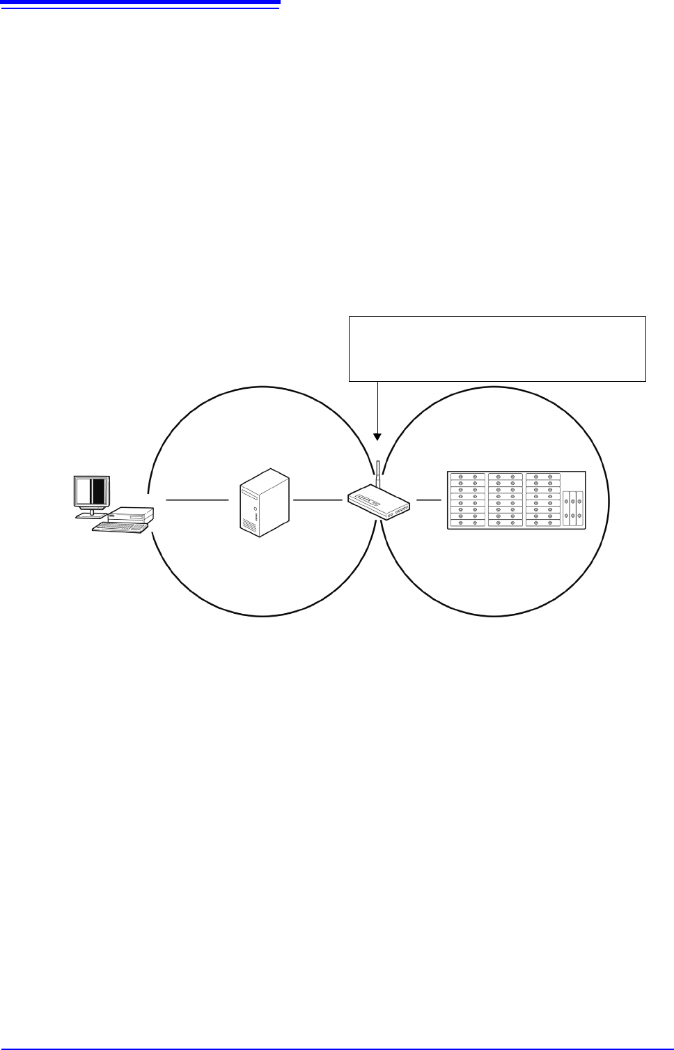
As the figure below indicates, install the router between the DHCP server and
the instrument. Contact your dealer or Hioki representative for more information.
Router installation
WAN port: IP address is automatically assigned by a DHCP server.
LAN port : Static IP address needs to be manually assigned.
Set up port forwarding to forward incoming traffic to this instrument
when the router receives it from PC.
Model MR8740
Model MR8741
Router
DHCP Server
PC
IP adress range assigned by DHCP server. Use static IP address.
15.1 LAN Settings and Connection (Before Using FTP/Internet Browser/Command Communications)
317
12
Chapter 15 Connection to a Computer
14
15
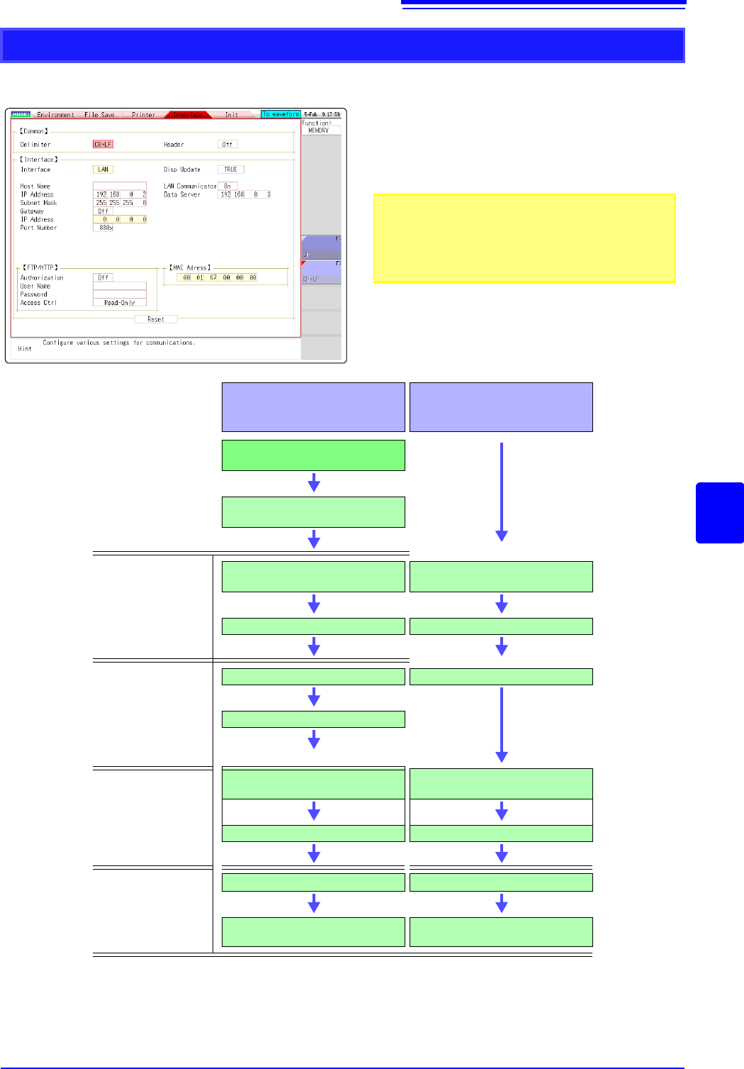
Click [SYSTEM] in the right-click menu to display the Communications sheet. According to the intended use,
make settings as outlined below.
LAN Setup Workflow
Use the mouse to move the flashing cursor
and select a setting item.
See: "7.1.3 Alphanumeric Input" (p.141)
For details on each setting, see "Setting Items" (p.315).
About the network
For IP address information and other details about the net-
work you are using, contact your network administrator.
(8)
(1)
(2)
(3)
(4)
(5)
(6)
(7)
Purpose
When Connecting to an
Existing Network
When Configuring a New
Network with a PC and
This Instrument
Use specified IP address and
connect to network
To assign a name to the instrument,
make a setting for (1) [Host Name]
Settings within same
network
(2) Set [IP Address] for this
instrument
(2) Set [IP Address] for this
instrument
(3) Set [Subnet Mask] (3) Set [Subnet Mask]
Settings for connecting
to other network
(Using gateway)
(4) [Gateway]: On
(4) Set [Gateway]: Off
(5) Set gateway [IP Address]
Settings for remote
operation and data
acquisition by using
Model 9333 LAN
Communicator
(6) Set [LAN Communicator]
to ON.
(6) Set [LAN Communicator]
to ON.
(7) Set IP address for [Data srvr] (7) Set IP address for [Data srvr]
Connect
(8) Execute [Reset] (8) Execute [Reset]
Connect with straight-through cable
See: "15.1.2"(p.318)
Connect with crossover cable
See:"15.1.2"(p.318)
15.1 LAN Settings and Connection (Before Using FTP/Internet Browser/Command Communications)
318
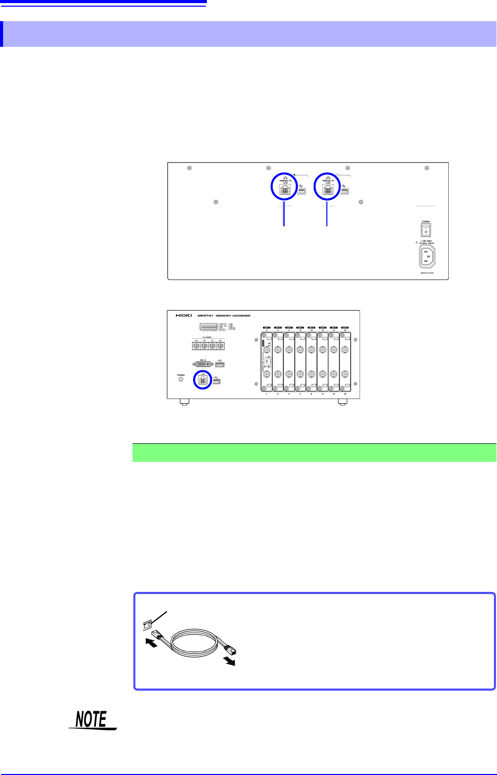
Connect the instrument to a PC with a LAN cable as follows.
1. Plug the LAN cable (100BASE-TX compliant) into the 100BASE-TX connector
on the rear of the instrument in the case of the MR8740 and on the front of the
instrument in the case of the MR8741.
2. Connect the above LAN cable to the PC. There are two ways to do this.
You can monitor and control the instrument from a PC by connecting the instru-
ment to a hub with LAN cable (100BASE-TX cable).
15.1.2 Connecting Instrument and PC With LAN Cable
MR8740: Rear
MR8741: Front
LAN connec-
tor of block II
LAN connec-
tor of block I
1. Connecting the Instrument to a Network (Connecting the Instrument to a Hub)
Connection cable: Use one of the following.
• 100BASE-TX straight-through cable (maximum length 100 m, commercially
available)
(10BASE-T cable may also be used for 10BASE communications)
• 9642 LAN Cable (option)
100BASE-TX connector
Connect to hub
Connect the crossover adapter to the
100BASE-TX connector on the instrument.
In the case of MR8740, control is required for each block.