MR8740、MR8741_user_manual_eng_20191016H.pdf - 第162页
7.4 Converting Input Values (Sca ling Function) 150 The 9018-50 Clamp On Probe provides 0.2 V output when measu ring 10 A. So Scaling should be set to display 10 A with 0.2 V input (and 0 A with 0 V input). Selecting a C…
7.4 Converting Input Values (Scaling Function)
149
6
Chapter 7 Utility Functions
7
2
3
4
1
2
4
3
4
Procedure
To open the screen: Right-click and select [CHAN] [Each Ch] sheet
1
Enable the Scaling function.
Select
Move the flashing cursor to the [Disp] item.
2
Select the scaling conversion method.
Select
Move the flashing cursor to the [Method] item.
3
Specify the physical units.
Move the flashing cursor to the [Unit], and enter
the physical unit name. (Up to 7 characters)
See: "Entering Text" (p.141)
4
Enter the numerical values for conversion.
When you have selected [Ratio] (set conver-
sion ratio and offset)
Move the flashing cursor to the [Ratio] and [Off-
set] items.
Enter numerical values in each field.
When you have selected [2-Point] (set input val-
ues for two points and the values after conver-
sion)
Move the flashing cursor to the [Input P1], [Scale
P1], [Input P2], and [Scale P2].
Enter numerical values in each field.
Off No scaling.
NUM
Displayed as a decimal and includes a unit (m,
k, etc.).
SCI
Displayed as an exponent (the power of ten)
Ratio Specify by conversion ratio.
Point
Specify by two points.
-9.9999E+9 to 9.9999E+9
-9.9999E+9 to 9.9999E+9
Input example:
Decimal1.2345 mV
Exponent1.2345E-03V
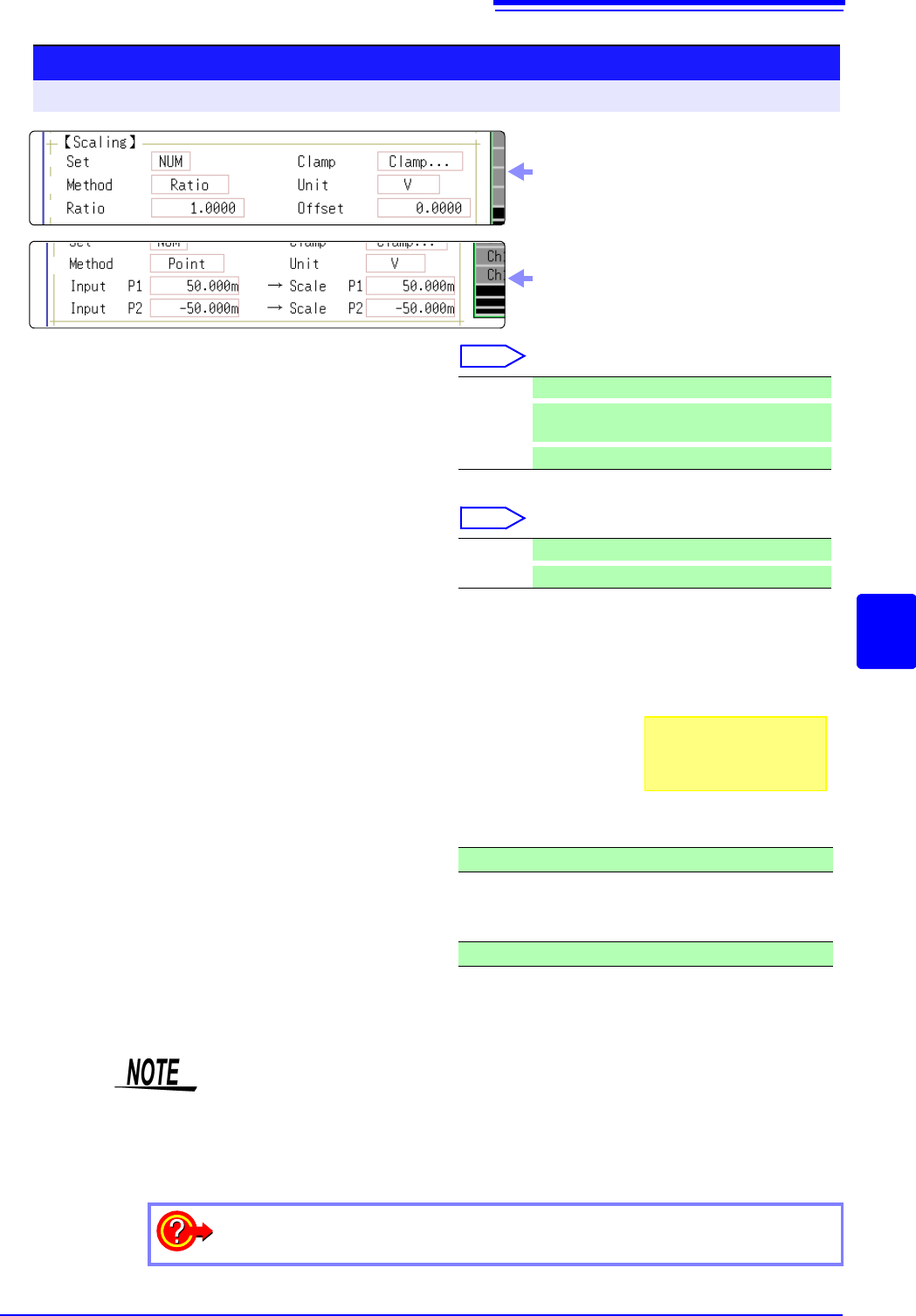
Display selecting [Ratio] for [Method] item
Display selecting [Point] for [Method] item
• When saving text or results of numerical calculation, some characters and
symbols used for display on the instrument will be converted as follows.
(MR8740/MR8741 display saved string)
•
2
^2,
3
^3, ~u, ~o, ~e, °~c ,
±~+, (display only)uE, °C (display only)C
To enter the current input value as is for P1 or P2
Select [Monitor Val].
7.4 Converting Input Values (Scaling Function)
150
The 9018-50 Clamp On Probe provides 0.2 V output when measuring 10 A. So
Scaling should be set to display 10 A with 0.2 V input (and 0 A with 0 V input).
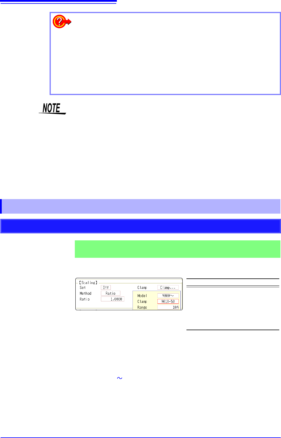
Selecting a Clamp Type ___________________________________________
1. Move the flashing cursor to the [Clamp] item, and select [Select].
The flashing cursor moves to the [Model] item.
2. Select [9000 ].
The flashing cursor moves to the [Clamp].
3. Select [9018-50] from the clamp list and select [Confirm].
Units, scaling method, and ratio are set automatically.
4. Select the same range of the clamp when using the range selection type.
Select [10A] here.
To reset Scaling settings:
Move the flashing cursor to the [Setting], and select [Reset].
To copy the scaling setting to another channel
The Channel screen - [Scaling] sheet can be used to copy a setting.
See: "7.8 Copying settings to other channels (calculation No.) (Copy function)" (p.160)
Using the Scaling and Variable functions (p.155) in combination:
The full span of output from a sensor can be displayed. (p.157)
At factory shipping, automatic correction of the variable function (p.311) is set to
[On].
At this time, the Variable setting is altered so that it is linked to (dependent upon)
the vertical axis (voltage axis) range and scaling settings. If you want the Vari-
able function setting to take priority, use either of the following procedures:
• Set Scaling first, and then set the Variable function
• Set a Variable value before Scaling, and then set Scaling.
When automatic correction of the Variable function (Variable Auto Adjustment) is
disabled ([Off]), the Scaling and Variable settings are unlinked (independent of
one another).
7.4.1 Scaling Setting Examples
Using a Clamp-On Probe
Example 1
Measure with the 10 A range of the Model 9018-50 Clamp On Probe and
display the measured data in units of [A] (Amperes)
Setting Items Setting Choice
Disp NUM or SCI
Clamp 9018-50
Unit
*
A
Method
*
Ratio
Ratio
*
50.000
*: Set automatically when clamp is selected.
7.4 Converting Input Values (Scaling Function)
151
6
Chapter 7 Utility Functions
7
However, you may need to switch the vertical axis (voltage axis) range to suit
actual input values.
For example, to display ±0.2 V at full scale, set the vertical display to 20 mV per
division (the instrument's 20 mV/div range)
For the rated capacity and rated output, consult the calibration record of the
strain gauge transducer to be used. Set as follows:
With scaling, signals from the sensor are
acquired as current values.
A/B cursors and gauges are displayed
with current (Ampere) values.
See: Upper/lower limit: (p.134)
Cursor A/B value: (p.120)
Before Scaling
After Scaling
[A]
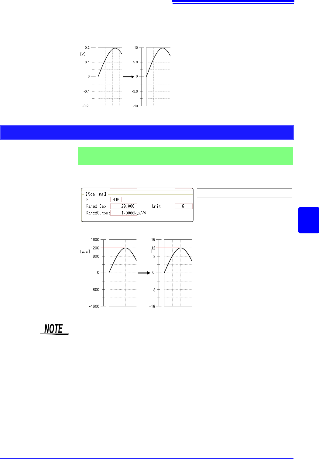
Using Model 8969 or U8969 Strain Unit
Example 2
Using the 20 G rated capacity and a strain gauge transducer with 1000
V/V rated output, display measured data in units of [G]
Setting Items Setting Choice
Disp NUM
Unit G
Rated Cap
(Rated capacity)
20 [G]
Rated Output 1k
By using the Scaling function, signals
from the strain gauge transducer are
acquired as physical values.
A/B cursors and gauges are displayed
as physical (G) values.
See: Upper/lower limit: (p.134)
Cursor A/B value: (p.120)
Before Scaling
After Scaling
[G]
Set the parameters such that the rated capacity divided by two times the rated output is
less than or equal to 9.9999
x 10
9
.